Fuse circuit

a fuse circuit and circuit technology, applied in the field of fuse circuits, can solve problems such as destabilizing the operation of fuse circuits, and achieve the effect of reducing peak curren

Active Publication Date: 2005-07-07
SK HYNIX INC
View PDF9 Cites 12 Cited by
  • Summary
  • Abstract
  • Description
  • Claims
  • Application Information

AI Technical Summary

Benefits of technology

[0018] Accordingly, it is an object of the present invention to provide a fuse circuit comprising a fuse set for selectively performing a reset operation only in a reset mode of the fuse circuit, thereby reducing peak current.

Problems solved by technology

As a result, the conventional fuse circuit requires a large amount of current when the reset operation of the fuse circuit is performed, and the generated peak current causes power noise of the fuse, thereby destabilizing the operation of the fuse circuit.

Method used


Image

  • Fuse circuit
  • Fuse circuit
  • Fuse circuit

Examples


Embodiment Construction

[0025] The present invention will be describe in detail with reference to the accompanying drawings.

[0026]FIG. 3 is a diagram of a fuse circuit according to an embodiment of the present invention.

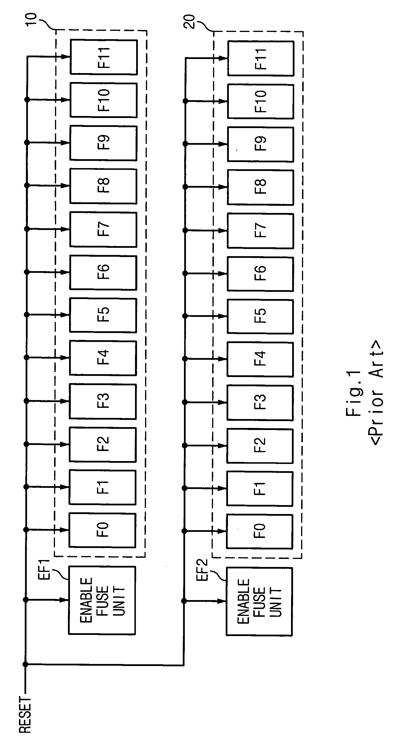
[0027] In an embodiment, the fuse circuit comprises enable fuse units EF1 and EF2 connected in parallel to fuse sets 100 and 200, respectively.

[0028] The enable fuse units EF1 and EF2 have current flowing basically at a reset mode, and control the enable state of the fuse sets 100 and 200.

[0029] The fuse sets 100 and 200 each corresponding to the enable fuse units EF1 and EF2 comprise a plurality of fuses F0˜F11 connected in parallel, respectively. The current flowing in the plurality of fuses F0˜F11 is controlled by the enable fuse units EF1 and EF2. The fuse sets 100 and 200 are reset depending on output state from the enable fuse units EF1 and EF2, respectively.

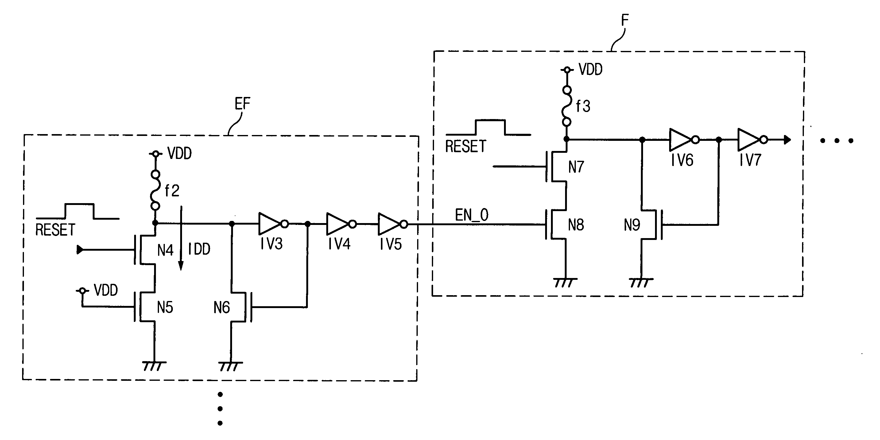
[0030]FIG. 4 is a circuit diagram of the enable fuse unit EF and the fuse set F of FIG. 3.

[0031] The enable fuse unit EF c...


PUM


Abstract

A fuse circuit comprises a plurality of enable fuse units and a plurality of fuse sets. Current flows at a reset mode in the plurality of enable fuse units, and the flowing of current is controlled by enable signals outputted from the plurality of enable fuse units in the plurality of fuse sets. In the fuse circuit, a fuse set connected to the end of the enable fuse unit whose fuse is disconnected selectively performs a reset operation, thereby reducing peak current to decrease the whole current consumption.

Description

BACKGROUND OF THE INVENTION [0001] 1. Field of the Invention [0002] The present invention generally relates to a fuse circuit, and more specifically, to a technology of reducing current consumption by reducing peak current in a reset mode of a fuse circuit used for analysis and repair of memory design. [0003] 2. Description of the Prior Art [0004] Generally, a fuse circuit has been widely used for analysis and repair of memory design. [0005]FIG. 1 is a diagram of a conventional fuse circuit. [0006] The conventional fuse circuit comprises enable fuse units EF1 and EF2 , fuse sets 10 and 20 each corresponding to the enable fuse units EF1 and EF2. the fuse sets 10 and 20 comprise a plurality of fuse units F0˜F11. If the enable fuse units EF1 and EF2 are activated, the conventional fuse circuit operates the plurality of fuse units F0˜F11 to store address information of defect cells. [0007]FIG. 2 is a circuit diagram of the enable fuse units EF1 and EF2 or a plurality of fuse units F0˜F1...

Claims


Application Information

Patent Timeline
Patent Type & Authority Applications(United States)
IPC IPC(8): G11C5/00G11C29/00G11C11/34G11C17/16
CPCG11C17/16G11C7/02G11C7/20G11C29/787
Inventor YOON, HYUCK SOO
Owner SK HYNIX INC
Why Eureka
Try Eureka