Bias voltage generating circuit and memory of line decoder

A bias voltage, row decoder technology, applied in the field of memory, can solve the problem of large memory power loss, and achieve the effects of reducing power loss, reducing peak current, and small pull-down current

Active Publication Date: 2013-05-22
SHANGHAI HUAHONG GRACE SEMICON MFG CORP
View PDF7 Cites 14 Cited by
  • Summary
  • Abstract
  • Description
  • Claims
  • Application Information

AI Technical Summary

Problems solved by technology

[0010] The invention solves the problem of large power loss in the process of erasing the memory in the prior art

Method used


Image

  • Bias voltage generating circuit and memory of line decoder
  • Bias voltage generating circuit and memory of line decoder
  • Bias voltage generating circuit and memory of line decoder

Examples


Embodiment Construction

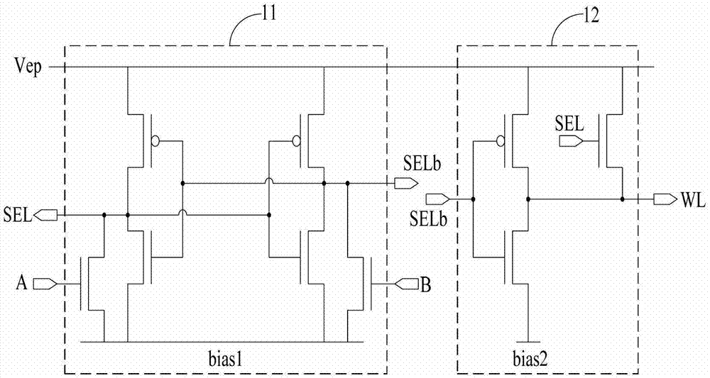
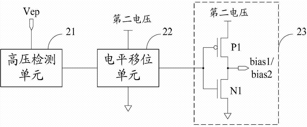
[0026] As described in the background technology, when the memory is performing an erase operation, figure 1 The first bias voltage bias1 and the second bias voltage bias2 required by the shown row decoder are provided by the same driving unit. After the erasing operation on the memory is completed, the first bias voltage bias1 and the second bias voltage bias2 will drop from the second voltage to the ground voltage. If the first bias voltage bias1 drops slowly, figure 1 The control signal generating unit 11 shown may output wrong third control signal SEL and fourth control signal SELb, causing logic confusion of memory erasing operation. therefore, figure 2The NMOS transistor N1 in the driving unit 23 shown must use a transistor with strong driving capability, so as to discharge quickly after the memory erasing operation, so that the first bias voltage bias1 drops rapidly. However, the rapid discharge results in a large peak current flowing into the ground, which increases...


PUM


Abstract

The invention discloses a bias voltage generating circuit and a memory of a line decoder. The bias voltage generating circuit of the line decoder is suitable for providing a first bias voltage and a second bias voltage to the line decoder. The bias voltage generating circuit of the line decoder comprises a high voltage detecting unit, a level shifting unit, a first driving unit and a second driving unit, wherein the high voltage detecting unit is suitable for detecting the power supply voltage of the line decoder and outputting a detection control signal; the level shifting unit is suitable for receiving the detection control signal and outputting a driving signal under the control of the detection control signal; the first driving unit is used for providing the first bias voltage under the control of the detection control signal; and the second driving unit is used for providing the second bias voltage under the control of the detection control signal. According to the technical scheme of the bias voltage generating circuit of the line decoder, the first bias voltage and the second bias voltage are respectively output through two driving units, so that the power loss in the process that a memory is subjected to erasure operation is reduced.

Description

technical field [0001] The invention relates to the technical field of memory, in particular to a bias voltage generating circuit of a row decoder and a memory. Background technique [0002] The storage unit of the memory (for example, flash memory Flash Memory) usually includes four leads: bit line (BL, Bit-Line), word line (WL, Word-Line), source line (SL, Source-Line) and baseline (SBL, Sub-Line), which are respectively coupled to the drain, gate, source and base of the MOS transistor. Generally, when performing an erase operation on a memory, a row decoder is required to apply a high voltage to a word line connected to a memory cell that performs an erase operation, and to apply a high voltage to a word line connected to a memory cell that does not perform an erase operation. Zero voltage bias voltage. [0003] figure 1 It is a schematic diagram of a circuit structure of an existing row decoder. refer to figure 1 , the row decoder includes a control signal generatio...

Claims


Application Information

Patent Timeline
Patent Type & Authority Applications(China)
IPC IPC(8): G11C8/08G11C8/10
Inventor 胡剑杨光军
Owner SHANGHAI HUAHONG GRACE SEMICON MFG CORP
Why Eureka
Try Eureka