Ultra-wideband antenna having an isotropic radiation pattern

a radiation pattern and ultra-wideband technology, applied in the field of ultra-wideband antennas, can solve the problems of serious radiation pattern distortion, destructive interference, difficult to use ultra-wideband communication systems in mobile terminals, etc., and achieve the effect of stable isotropic radiation pattern and excellent communication quality

Inactive Publication Date: 2005-07-07
SAMSUNG ELECTRONICS CO LTD
View PDF13 Cites 19 Cited by
  • Summary
  • Abstract
  • Description
  • Claims
  • Application Information

AI Technical Summary

Benefits of technology

[0020] It is a feature of an embodiment of the UWB antenna of the present invention to obtain stable isotropic radiation patterns in the horizontal plane in the range from a low frequency band to a high frequency band in the UWB frequencies. Accordingly, UWB communication systems employing the UWB antenna of an embodiment of the present invention can be used in mobile terminals without problems, and excellent communication quality can be obtained regardless of a position of the mobile terminal.

Problems solved by technology

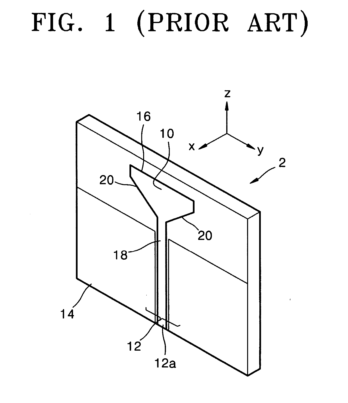
In other words, radio waves emitted by the current distributed in the Y-direction results in constructive interference in ±X-direction as for the low frequencies, but when the emitted radio wave approaches ±Y-axis, it results in destructive interference.
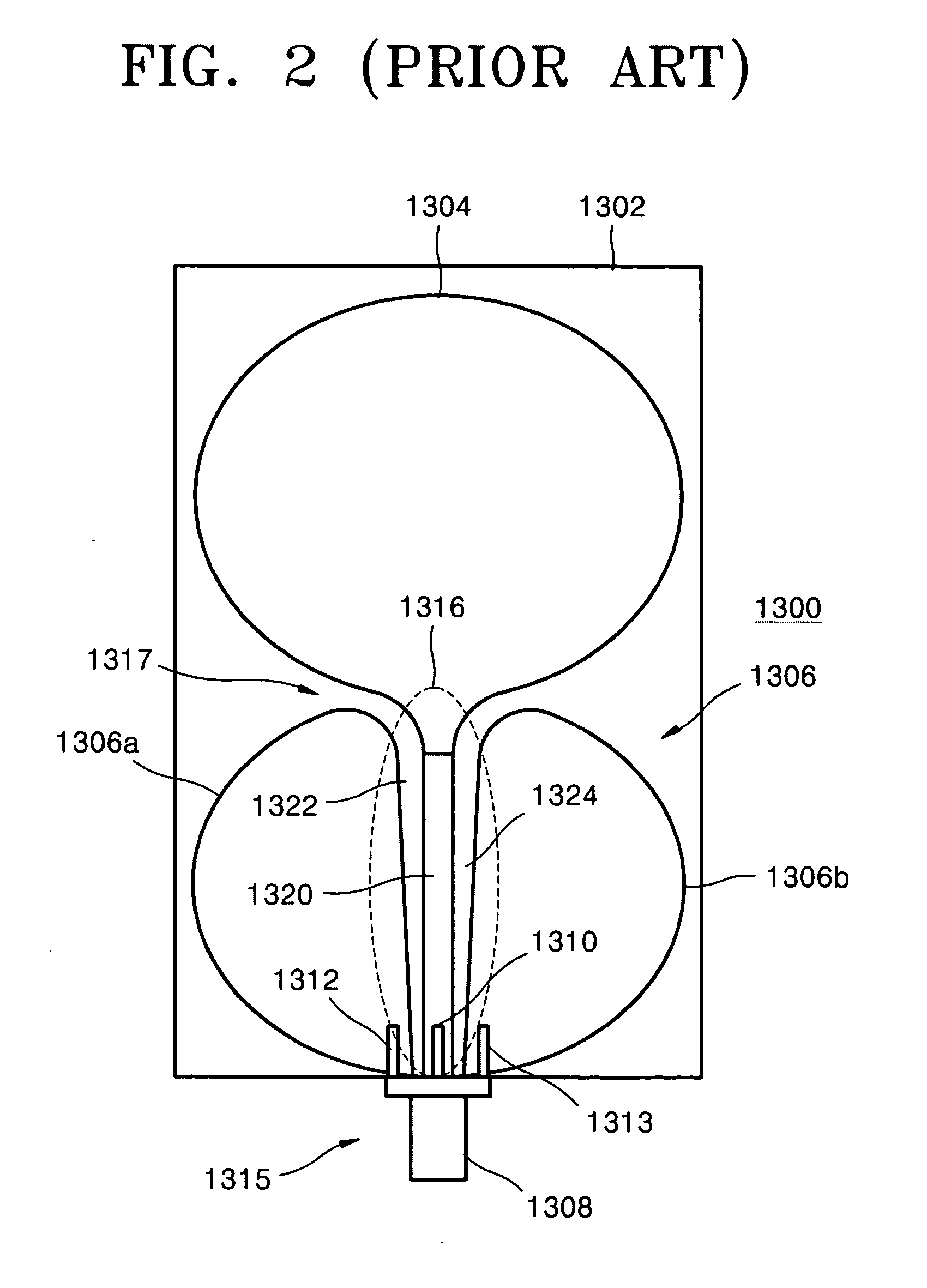
As described above, the conventional UWB antennas have problems in that, as the frequency increases, the radiation is concentrated in a specific direction, i.e., the radiation patterns are seriously distorted.
These problems with the conventional UWB antennas make it difficult to use UWB communication systems in mobile terminals.

Method used


Image

  • Ultra-wideband antenna having an isotropic radiation pattern
  • Ultra-wideband antenna having an isotropic radiation pattern
  • Ultra-wideband antenna having an isotropic radiation pattern

Examples


Embodiment Construction

[0031] Korean Patent Application No. 2003-88777, filed on Dec. 8, 2003, in the Korean Intellectual Property Office, and entitled: “Ultra-wide Band Antenna Having Isotropic Radiation Pattern,” is incorporated by reference herein in its entirety.

[0032] The present invention will now be described more fully with reference to the accompanying drawings, in which exemplary embodiments of the invention are shown. The invention may, however, be embodied in many different forms and should not be construed as being limited to the embodiments set forth herein; rather, these embodiments are provided so that this disclosure will be thorough and complete, and will fully convey the concept of the invention to those skilled in the art. In the drawings, the thickness of layers and regions are exaggerated for clarity. Like reference numerals in the drawings denote like elements, and thus their description will not be repeated.

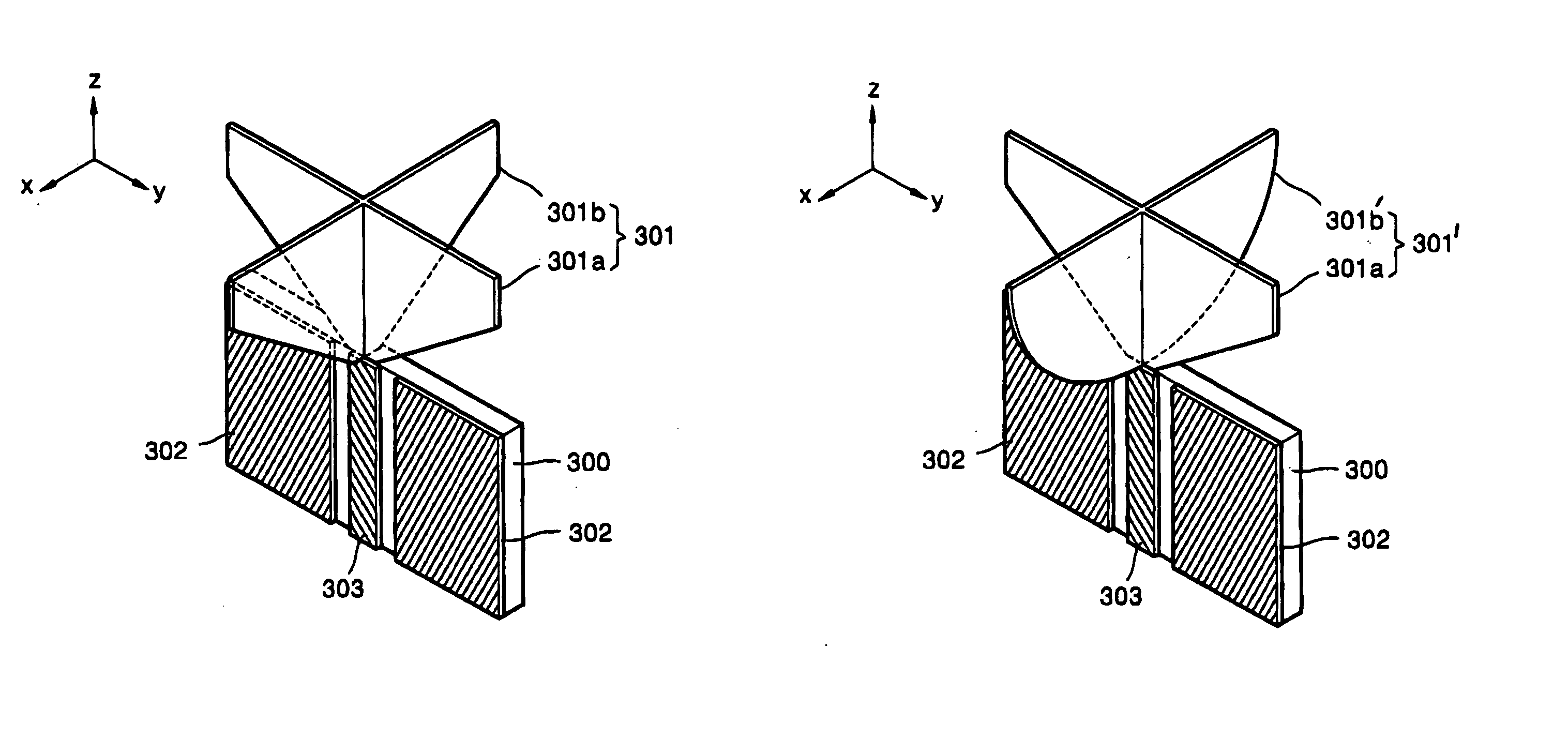
[0033] In FIGS. 4A and 4B, a UWB antenna having an isotropic radiation pa...


PUM


Abstract

An ultra-wideband antenna having an isotropic radiation pattern includes a support plate, a feed line on the support plate, a radiating element connected to the feed line to transmit and receive signals, and a ground plate spaced apart from the feed line and attached to the support plate. The radiating element has at least two intersecting conductive plates.

Description

BACKGROUND OF THE INVENTION [0001] 1. Field of the Invention [0002] The present invention relates to an antenna. More particularly, the present invention relates to an ultra-wideband (UWB) antenna having an isotropic radiation pattern. [0003] 2. Description of the Related Art [0004] Recent commercial deployment of UWB systems, which make use of a 3.1 GHz to 10.6 GHz frequency band, has increased interest in UWB antennas that can provide effective radiation patterns. UWB antennas may be designed using printed circuit board (PCB) technology. Therefore, UWB antennas can be manufactured at low cost. [0005] A UWB antenna interconverts electrical pulse signals and radio wave pulse signals. If radiating characteristics of the UWB antenna are directionally dependent, and the UWB communication system is not at a fixed location, e.g., mounted on a mobile terminal, communication quality is directionally dependent. Accordingly, it is desirable that UWB antennas emit pulse signals in all directi...

Claims


Application Information

Patent Timeline
Patent Type & Authority Applications(United States)
IPC IPC(8): H01Q1/38H01Q9/28H01Q9/40
CPCH01Q1/38H01Q9/40H01Q9/28
Inventor KWON, DO-HOONLEE, SEONG-SOO
Owner SAMSUNG ELECTRONICS CO LTD
Why Eureka
Try Eureka