

Control unit and method for controlling motor for use in printer, and storage medium storing control program
a control unit and printer technology, applied in the direction of program control, electric programme control, dc motor rotation control, etc., can solve the problems of long time and complex control
- Summary
- Abstract
- Description
- Claims
- Application Information
AI Technical Summary
Benefits of technology
Problems solved by technology
Method used
Image

Examples
first preferred embodiment
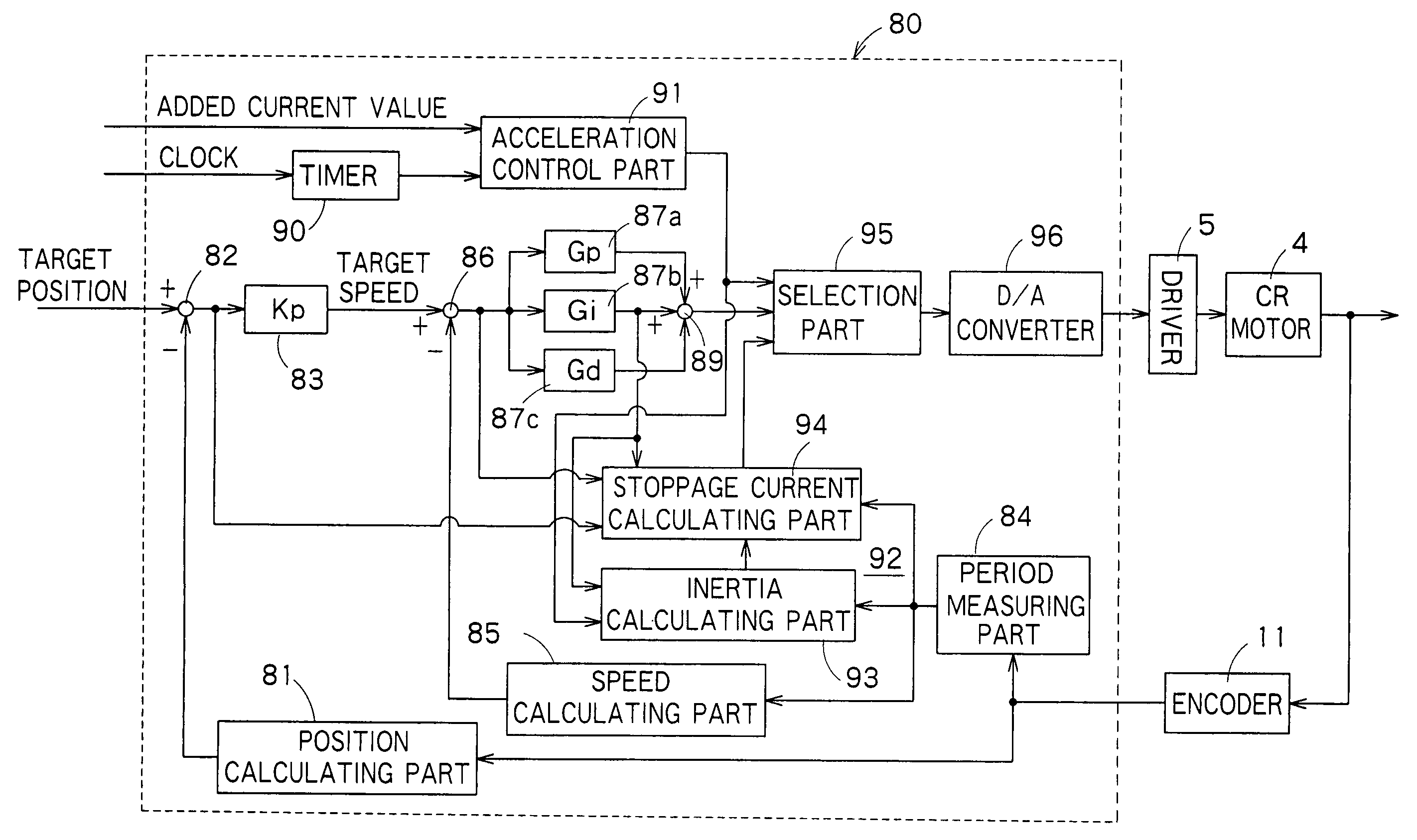
[0049] The construction of the first preferred embodiment of a control unit for controlling a motor for use in a printer according to the present invention is shown in FIG. 1. A controller 80 in this embodiment is used for controlling the carriage motor 4 (a DC motor) of the ink jet printer, and installed in the DC unit 6 explained with reference to FIG. 4.
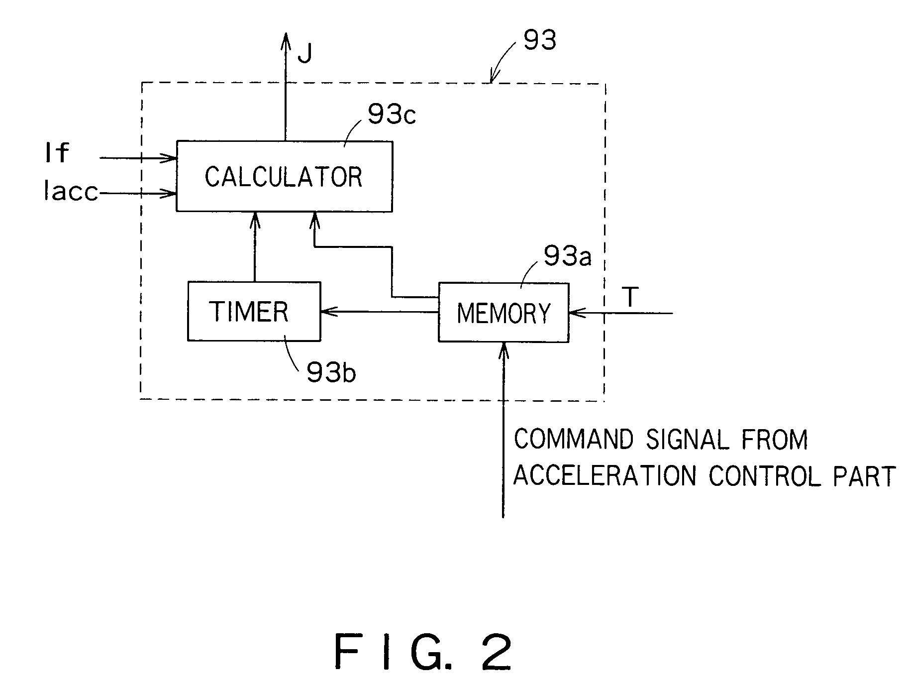
[0050] The controller 80 comprises a position calculating part 81, a subtracter 82, a target speed calculating part 83, a period measuring part 84, a speed calculating part 85, a subtracter 86, a proportional element 87a, an integrating element 87b, a differentiating element 87c, an adder 89, a timer 90, an acceleration control part 91, a stoppage control part 92 having an inertia calculating part 93 and a stoppage current calculating part 94, a selection part 95 and a D / A converter 96.
[0051] The position calculating part 6a is designed to detect the leading and trailing edges of each of the output pulses ENC-A and ENC-B of the ...
second preferred embodiment
[0087] The second preferred embodiment will be disclosed with reference to FIG. 9. The second embodiment is a method of controlling a motor for use in a printer. A control procedure is shown in FIG. 9.
[0088] Firstly, inertial of the carriage 3 is calculated based on angular acceleration of the CR motor 4 under carriage acceleration control, and current values applied to the CR motor 4 under carriage acceleration and constant speed control (see step F1 in FIG. 9).
[0089] Calculated next is a stoppage current for stopping the carriage 3 at the target position based on the calculated inertia, an angular velocity of the CR motor 4 at carriage deceleration, a current value applied to the CR motor 4 under carriage constant control, and the stoppage constant TBRK (see step F2 in FIG. 9).
[0090] The calculated stoppage current is then applied to the CR motor 4 for carriage stoppage (see step F3 in FIG. 9).
[0091] The steps F2 and F3 in FIG. 9 are the steps for controlling a current applied...
third preferred embodiment
[0093] Referring to FIGS. 10 and 11, the third preferred embodiment of the present invention will be described below. This preferred embodiment relates to a storage medium, in which a control program for controlling a motor for use in a printer has been stored. FIGS. 10 and 11 are a perspective view and block diagram showing an example of a computer system 130 which uses a storage medium, in which a print control program in this preferred embodiment has been recorded.
[0094] In FIG. 10, the computer system 130 comprises a computer body 130 including a CPU, a display unit 132, such as a CRT, an input unit 133, such as a keyboard or mouse, and a printer 134 for carrying out a print.
[0095] As shown in FIG. 11, the computer body 131 comprises an internal memory 135 of a RAM, and a built-in or exterior memory unit 136. As the memory unit 136, a flexible or floppy disk (FD) drive 137, a CD-ROM drive 138 and a hard disk drive (HD) unit 139 are mounted. As shown in FIG. 10, a flexible disk...
PUM
 Abstract
Description
Claims
Application Information