

Elongated flexible lighting equipment and fabricating method of same
- Summary
- Abstract
- Description
- Claims
- Application Information
AI Technical Summary
Benefits of technology
Problems solved by technology
Method used
Image

Examples
first embodiment
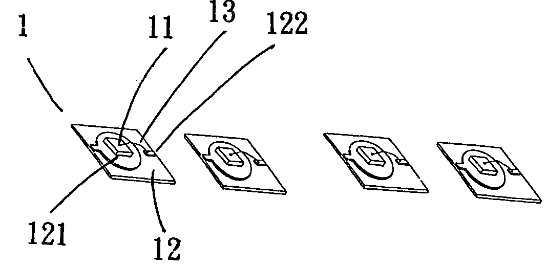
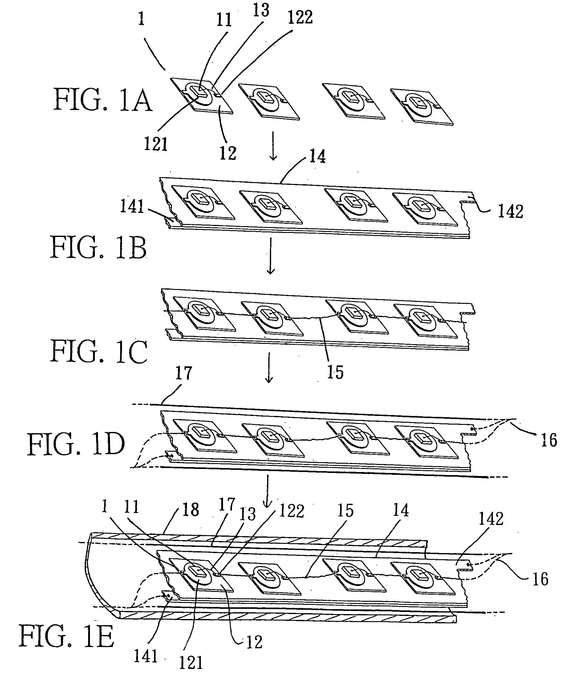
[0024]FIGS. 1A to 1E show the schematic views illustrating the fabrication steps in a first embodiment, the fabrication comprises the steps: [0025] Step 1: Disposing LED unpacked chip or its original element in a single substrate 12 in which containing at least two electrodes, connecting one of the two to an electrode 121 of the substrate 12, and the other one to the other electrode 122 of the substrate 12 with a welding wire 13. [0026] Step 2: Arranging longitudinally several LED lighting element 1 in an elongated LED substrate 14 which is provided with electrodes 141, 142 each at one terminal. [0027] Step 3: Connecting several LED lighting elements 1 in cascade with a power supply busbar 15 to form a string of lighting source. [0028] Step 4: Connecting multi-polar or multi-circuit power supply busbars 15 together with connectors 16 to form a variety of elongated lighting effects. [0029] Step 5: Preparing another power supply busbar 17 in parallel to the power supply busbar 15. [00...
second embodiment
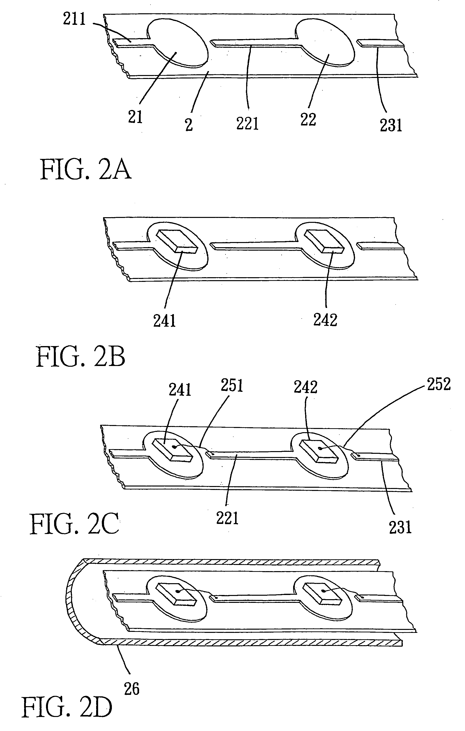
[0032]FIGS. 2A to 2D are the schematic views illustrating the fabrication steps in a second embodiment, it comprises the steps: [0033] Step 1: Fabricating an elongated substrate 2 firstly, and then disposing several electrodes 21, 22 . . . longitudinally on the upper surface of the elongated substrate 2. [0034] Step 2: Extending extension portion 211, 221, 231 in the same direction from each of the electrodes 21, (22) . . . , and installing a LED unpacked chip or original element 241 (242) on each electrode 21 (22) . . . [0035] Step 3: Connecting each LED unpacked chip or original element 241(242) with the adjacent extension portion 221 (231) with a welding wire 251(252) to form a string of lighting source. [0036] Step 4: Enclosing the string of lighting source with an inner insulation housing 26,
wherein the elongated substrate 2 is made of an elongated soft insulated material which is a longitudinally extruded mono- or multi-colored plastic transparent, or semi-transparent materia...
third embodiment
[0037]FIGS. 3A to 3F are the schematic views illustrating the fabrication steps in a third embodiment, it comprises the steps: [0038] Step 1: Fabricating an elongated substrate 3 firstly, it is a LED substrate made of a soft insulated material such as a PC board, and then disposing several electrodes 31, 32 . . . longitudinally on the PC board with printed wires. [0039] Step 2: Extending extension portions 311, 321, 331 in the same direction from each of the electrodes 31 (32), and installing a LED unpacked chip or original element 341 (342) on each electrode 31 (32) . . . [0040] Step 3: Connecting each LED unpacked chip or original element 341 (342) with the adjacent extension portion 321 (331) with a welding wire 351 (352) to form a string of lighting source. [0041] Step 4: Enclosing the lighting source with a soft fixing material 36. [0042] Step 5: Preparing another power supply busbar 37 in parallel to the string of lighting source, and connecting the multi-polar or multi-circui...
PUM
 Abstract
Description
Claims
Application Information