Devices comprising multiple capillary inducing surfaces

a capillary inducing surface and device technology, applied in the field of capillary, can solve the problems of inability to achieve the same level of access to assay equipment or reagents in non-laboratory settings, and inability to meet the requirements of laboratory or field settings. , to achieve the effect of enhancing reaction kinetics, easy manipulation, and increasing assay volum

Inactive Publication Date: 2005-07-07
BIOSITE INC
View PDF38 Cites 15 Cited by
  • Summary
  • Abstract
  • Description
  • Claims
  • Application Information

AI Technical Summary

Benefits of technology

[0038] Disclosed herein for the first time in the art are assay device structures that accomplish the objectives of permitting a compact assay device configuration together with enhanced assay volumes. When conducting an assay in laboratory or non-laboratory settings, it is frequently desired that only a small amount of sample to be assayed be provided, compact devices are well suited to this aspect. Additionally, devices comprising microcapillaries are generally preferred because they are readily manipulated and they provide for enhanced reaction kinetics. It is advantageous for the device to be approximately the size of a human hand. This size facilitates manipulation of the device, making it easier for the individual conducting the assay to place any assay reactants into the device. Additionally, devices which are readily held in the human hand are of a size that facilitates packing, shipping and storage of the devices.
[0039] However, small devices have limited capacity, and this capacity can be insufficient for a requisite reaction volume or assay volume. The assay device structures disclosed herein achieve fluid flow through an assay device; advantageously, this fluid flow is accomplished by use of capillarity without a need to employ any additional external force such as hydrostatic pressure. As discussed in greater detail below, preferred device structures comprise a capillary region of the device that permits compact design configurations, while still achieving an effective capillary force to result in fluid flow, while increasing the fluid capacity of the device.

Problems solved by technology

Additionally, non-laboratory settings often lack the same level of access to assay equipment or reagents found in laboratories.
A problem with the use of capillarity as a means to achieve proximal-to-distal movement through a device concerns the fluid volume required to perform an assay, i.e., the “assay volume.” An assay result is often achieved only when the sample has traveled through the device.
However, in order to achieve sufficient distal capillarity in a compact device, dimensions in the distal areas are often extremely minute.
If sample and non-sample fluids must be accommodated distally, devices with sufficient capillarity and the requisite capacity have highly impractical configurations for laboratory or field settings.
If a capillary in a distal region is made larger to accommodate an assay volume (a reaction volume and other needed volumes), the drop in capillarity in that region often impairs fluid flow into the region.

Method used


Image

  • Devices comprising multiple capillary inducing surfaces
  • Devices comprising multiple capillary inducing surfaces
  • Devices comprising multiple capillary inducing surfaces

Examples


example 1

[0069] In this embodiment, fluid was found to flow between a proximal region comprising an array of structures as depicted in FIG. 7B, and a distal region comprising an array of capillarity-inducing structures such as depicted in FIG. 8B. The effective capillarity of the proximal region was believed to be induced by the 12 micron distance from the inner surface of the lid to the upper surface of the base, i.e., capillary force induced in a “vertical” direction. The effective capillarity of the distal region was believed to be induced by the 10.2 micron distance between parallel walls of adjacent capillarity-inducing structures, i.e., capillary force induced in a “horizontal” direction.

[0070] The proximal region comprised a height of 12 microns from the inner surface of the lid to the upper surface of the base; the height of the distal region was 22 microns from the inner surface of the lid to the upper surface of the base. Accordingly, the distal region had a greater capacity than ...

example 2

[0071] In this embodiment, fluid was found to flow between a proximal region comprising an array of structures such as found in FIG. 6B, and a distal region comprising an array of capillarity-inducing structures such as depicted in FIG. 9B.

[0072] The effective capillarity of the proximal region was believed to be induced by the 12 micron distance from the inner surface of the lid to the upper surface of the base, i.e., capillary force induced in a “vertical” direction. The effective capillarity of the distal region was believed to be induced by the 12 micron distance between parallel walls of adjacent capillarity-inducing structures, i.e., capillary force induced in a “horizontal” direction.

[0073] The proximal region comprised a height of 12 microns from the inner surface of the lid to the upper surface of the base; the height of the distal region was 22 microns from the inner surface of the lid to the upper surface of the base. Accordingly, the distal region had a greater capacit...

example 3

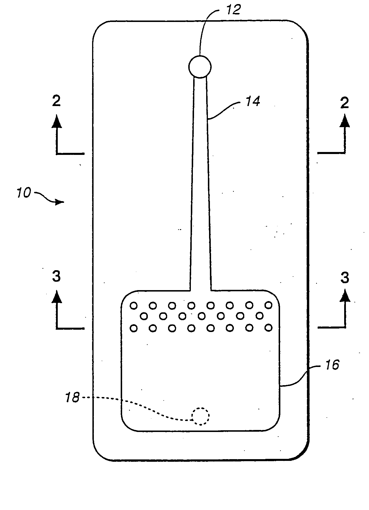
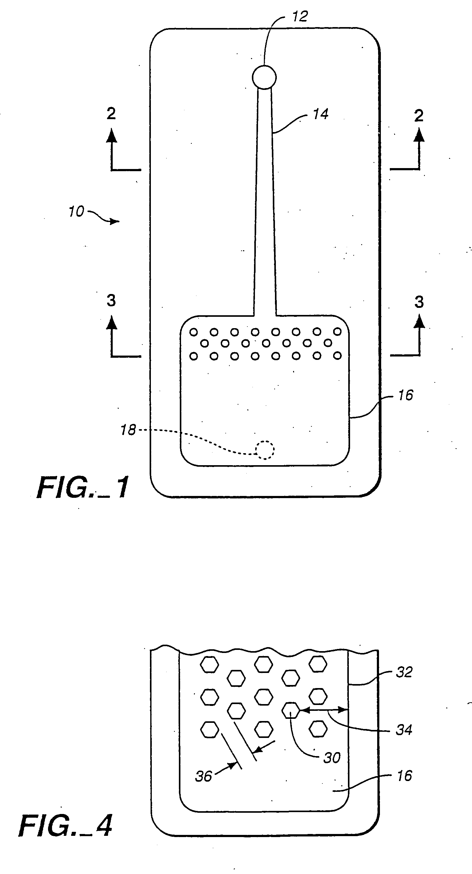
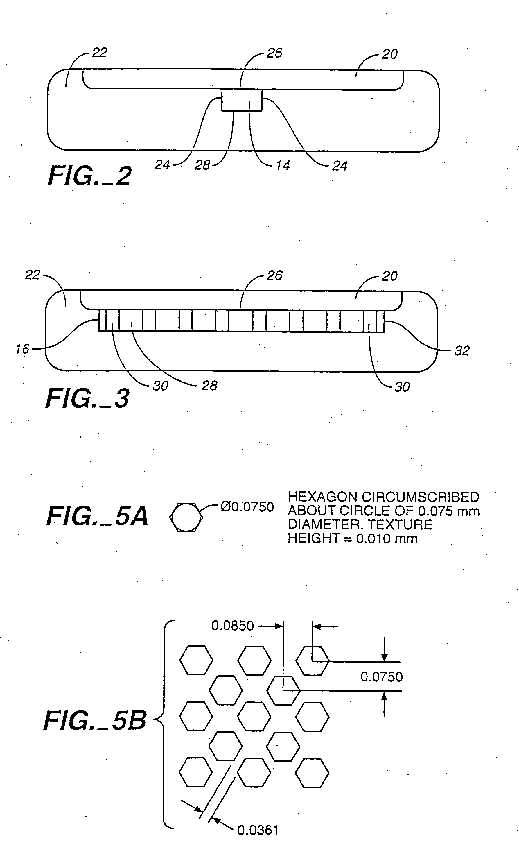
[0074] In this embodiment, fluid was found to flow between a proximal region comprising an array of structures such as depicted in FIG. 5B, and a distal region comprising an array of capillarity-inducing structures such as depicted in FIG. 8B.

[0075] The effective capillarity of the proximal region was believed to be induced by the 12 micron distance from the inner surface of the lid to the upper surface of the base, i.e., capillary force induced in a “vertical” direction. The effective capillarity of the distal region was believed to be induced by the 10.2 micron distance between parallel walls of adjacent capillarity-inducing structures, i.e., capillary force induced in a “horizontal” direction.

[0076] In this embodiment, the height of the first distal region was 12 microns from the inner surface of the lid to the upper surface of the base; the height in the distal region was 22 microns from the inner surface of the lid to the upper surface of the base. Accordingly, the distal reg...


PUM

PropertyMeasurementUnit
diameteraaaaaaaaaa
distanceaaaaaaaaaa
distanceaaaaaaaaaa

Abstract

Assay device structures for a device where fluid flows from a one region to another. The device structures comprising one or more capillarity-inducing structures; where the capillarity-inducing structure induces capillary force along an axis that is essentially perpendicular to the axis along which capillary force induced in another region of the device.

Description

RELATED PATENT APPLICATIONS [0001] This application is a continuation of, and claims priority from, U.S. patent application Ser. No. 09 / 612,815, filed on Jul. 10, 2000 and U.S. patent application Ser. No. 08 / 749,702, filed on Nov. 15, 1996. The content of both applications are hereby incorporated herein by reference.FIELD OF THE INVENTION [0002] This application concerns capillarity, also referred to as capillary action or capillary force. In a particular embodiment, the invention concerns an assay device that comprises multiple capillary force-inducing surfaces having distinct positional orientations. BACKGROUND ART [0003] With the advent of field-based testing and point of care testing in hospitals, it has become increasingly important to develop diagnostic products which are simple, rapid and convenient for use. In these contexts, results are generally needed rapidly, with a minimum of time given to the performance of a test. Providing an assay result in minutes allows prompt act...

Claims


Application Information

Patent Timeline
Patent Type & Authority Applications(United States)
IPC IPC(8): B01L3/00
CPCB01L3/5023B01L3/502707B01L3/50273B01L2400/086B01L2300/0825B01L2400/0406B01L3/502746
Inventor BUECHLER, KENNETH FRANCIS
Owner BIOSITE INC
Why Eureka
Try Eureka