
Foot control for dental instruments

a technology for dental instruments and foot control, applied in the field of foot control, can solve the problems of inability to use the foot of the operator, crowded space, and limited space, and achieve the effect of improving the foot control and reducing clutter

Inactive Publication Date: 2005-07-07
MACE JAMES G
View PDF9 Cites 29 Cited by
  • Summary
  • Abstract
  • Description
  • Claims
  • Application Information

AI Technical Summary

Benefits of technology

[0009] Among the various features and advantages of the present invention may be noted the provision of an improved foot control that reduces clutter on the floor between the dental professional(s) and the patient.
[0012] A fourth feature is the provision of such a foot control that eliminates all cords, tubes, and cables from the foot control during operation.

Problems solved by technology

Single-lever foot controls suffer from the disadvantage that they may be actuated from essentially a single position, so that as the dental professional moves around the patient it may be necessary to move the foot control.
In addition, dual-lever foot controls are available, but they suffer from essentially the same problem.
It has been found that the cord connecting these prior art foot controls (often called “rheostats” in the art) to the dental instrument and its point of connection to the foot control itself pose problems for the dental professional operator.
This space is often crowded and limited, due to casters, feet, and other cords.
In addition, the design of many available foot controls dictates that the point of connection of the cord to the foot control (rheostat) is not usable by the operator's foot.

Method used


Image

  • Foot control for dental instruments
  • Foot control for dental instruments
  • Foot control for dental instruments

Examples


Embodiment Construction

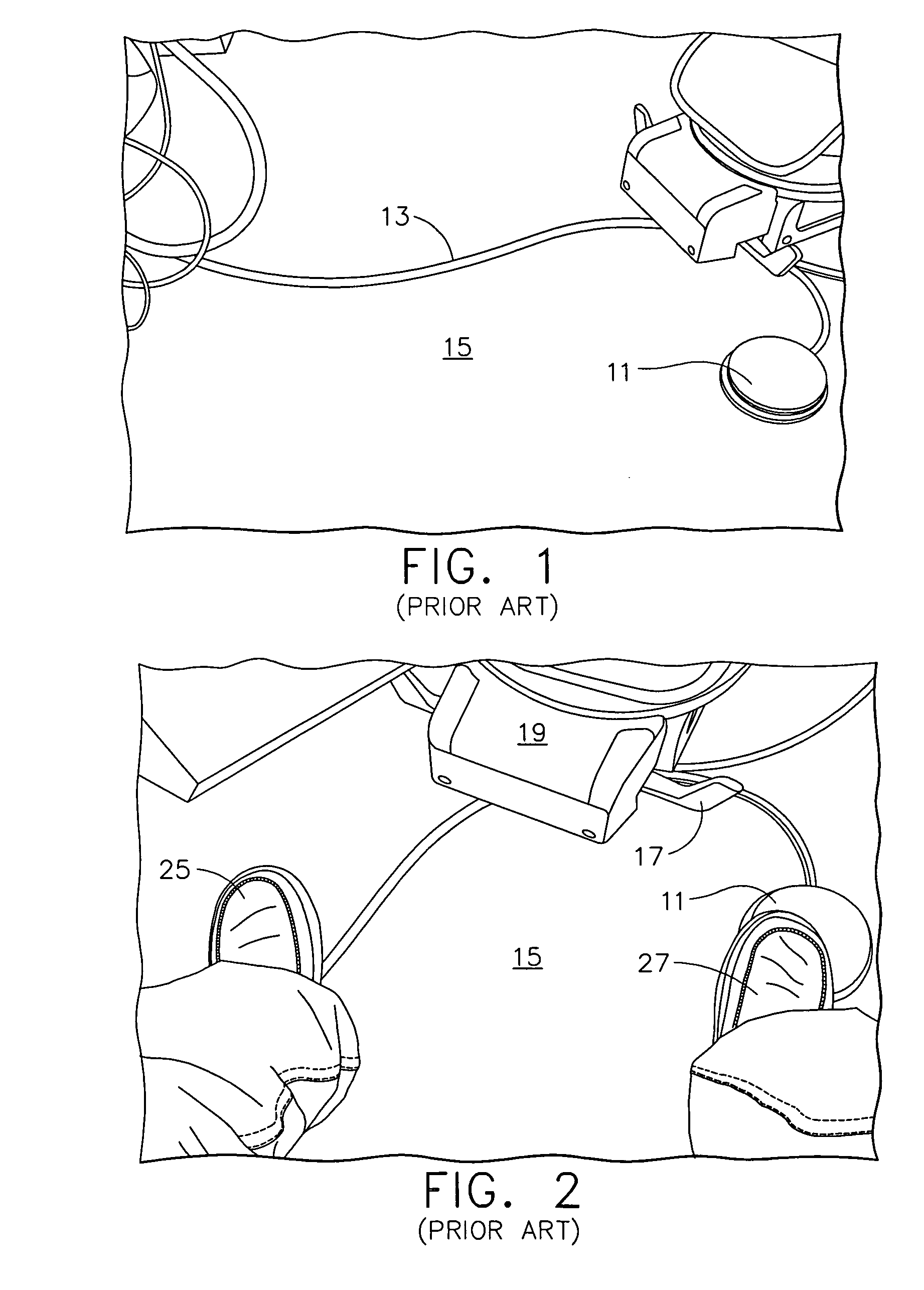
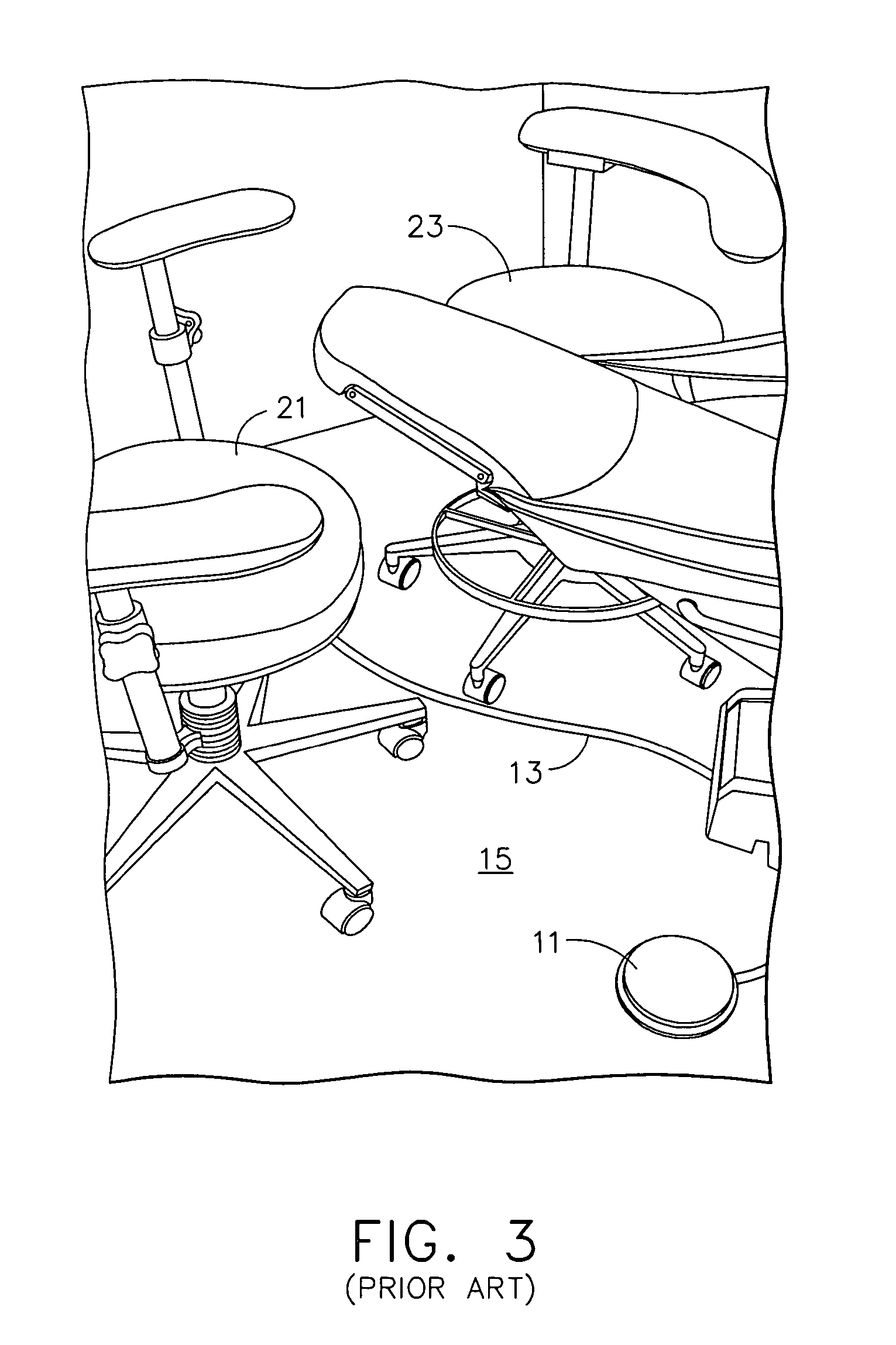
[0031] Referring to the accompanying drawings in which like reference numbers indicate like elements, FIG. 1 illustrates a prior art foot control (rheostat) 11 connected to a dental instrument (not shown) by a cable or tube 13 (depending upon whether the dental instrument is air-powered or electrically powered). As seen in FIGS. 1-3, the cable / tube stretches across the floor 15 of the dentist's office, potentially interfering with a control lever 17 of the patient's chair 19, with free movement of the dentist's chair 21, or with free movement of the dental hygienist's chair 23. FIG. 2 illustrates, for example, the cable / tube interfering with the placement of the dentist's left foot 25 while the right foot 27 is operating the prior art foot control.

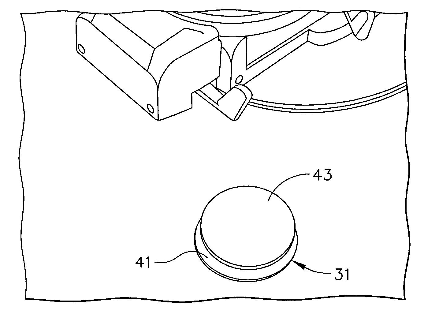
[0032] In FIGS. 4 and 5, a replacement foot control (rheostat) 31 for prior art foot control 11 is shown. Foot control 31 is cordless—the cable / tube 13 of the prior art device is eliminated. As is explained in detail below, foot control 3...


PUM


Abstract

A foot control for a dental instrument includes a control signal generator and a foot-operated actuator to manually provide control information to the control signal generator. The control signal generator is responsive to the control information to generate and transmit an electromagnetic signal corresponding to the control information to a receiver associated with the dental instrument so as to control operation of the dental instrument. The control signal generator, the foot-operated actuator, and a power source are secured to a base adapted to rest on a floor of a dentist's office.

Description

CROSS-REFERENCE TO RELATED APPLICATIONS [0001] None. STATEMENT REGARDING FEDERALLY SPONSORED RESEARCH OR DEVELOPMENT [0002] Not Applicable. APPENDIX [0003] Not Applicable. BACKGROUND OF THE INVENTION [0004] 1. Field of the Invention [0005] This invention relates generally to a foot control for controlling the operation of dental instruments and, more particularly, to such a foot control that sends control signals electromagnetically. [0006] 2. Related Art [0007] Various foot-operated controllers (foot controls) are known for controlling operating parameters of dental instruments, such as drills, scalers and the like. Typical foot controls include a single lever that controls the speed of an air-powered or electrically-powered handpiece. Single-lever foot controls suffer from the disadvantage that they may be actuated from essentially a single position, so that as the dental professional moves around the patient it may be necessary to move the foot control. In addition, dual-lever fo...

Claims


Application Information

Patent Timeline
IPC IPC(8): A61C1/00G05G1/38G05G1/42H01H3/02H01H3/14
CPCA61B2017/00977A61C1/0023H01H3/14G05G1/42H01H3/0213G05G1/38
Inventor MACE, JAMES G.
Owner MACE JAMES G
Learn More