Arrangement and method for vascular anastomosis

a vascular anastomosis and arrangement method technology, applied in the field of arrangement and method of vascular anastomosis, can solve the problems of high morbidity and potential mortality, difficulties and shortcomings encountered, and none of them clearly or satisfactorily

Inactive Publication Date: 2005-07-07
SCHULZE DALE R
View PDF18 Cites 6 Cited by
  • Summary
  • Abstract
  • Description
  • Claims
  • Application Information

AI Technical Summary

Benefits of technology

[0027] According to the present invention, the foregoing drawbacks and disadvantages are clearly obviated in that novel methods and devices for anastomosis between a coronary artery or target vessel and a graft vessel are implemented prior to the formation of a fluid flow passageway between the vessels, thereby enabling the maintaining of a continued blood flow during the anastomosis.
[0030] Accordingly, it is a primary object of the present invention to provide a novel method of implementing anastomosis between two body vessels prior to the formation of a fluid flow passage way therebetween at the location of the anastomosis.

Problems solved by technology

Although numerous publications are currently available which to varying degrees concern themselves with this particular technology, none of them clearly or satisfactorily provide teachings regarding vascular anastomosis methods or devices which will provide for the joining of a target vessel, such as a coronary artery, to a graft vessel prior to the cutting of a fluid flow passageway between the graft vessel and the target vessel so as to generally, to a considerable degree, alleviate the difficulties and shortcomings encountered in the medical technology.
All of the foregoing publications require the termination of blood flow through the target vessel during implementing of the foregoing procedures, or necessitate lengthy surgical procedures which includes considerable risk to patients and which are subject to high degrees of morbidity and potential mortality while necessitating lengthy hospital stays for the patient.

Method used


Image

  • Arrangement and method for vascular anastomosis
  • Arrangement and method for vascular anastomosis
  • Arrangement and method for vascular anastomosis

Examples


Embodiment Construction

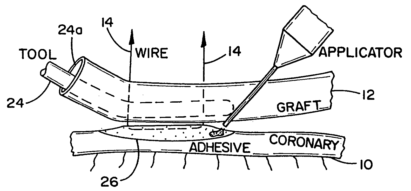
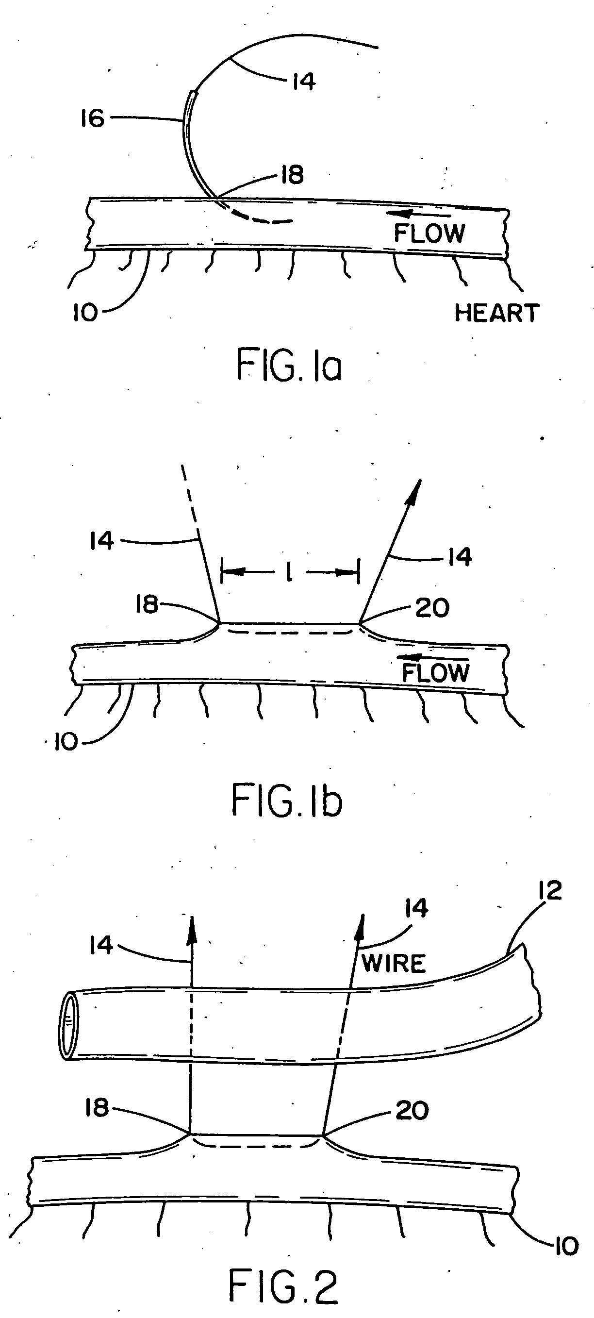
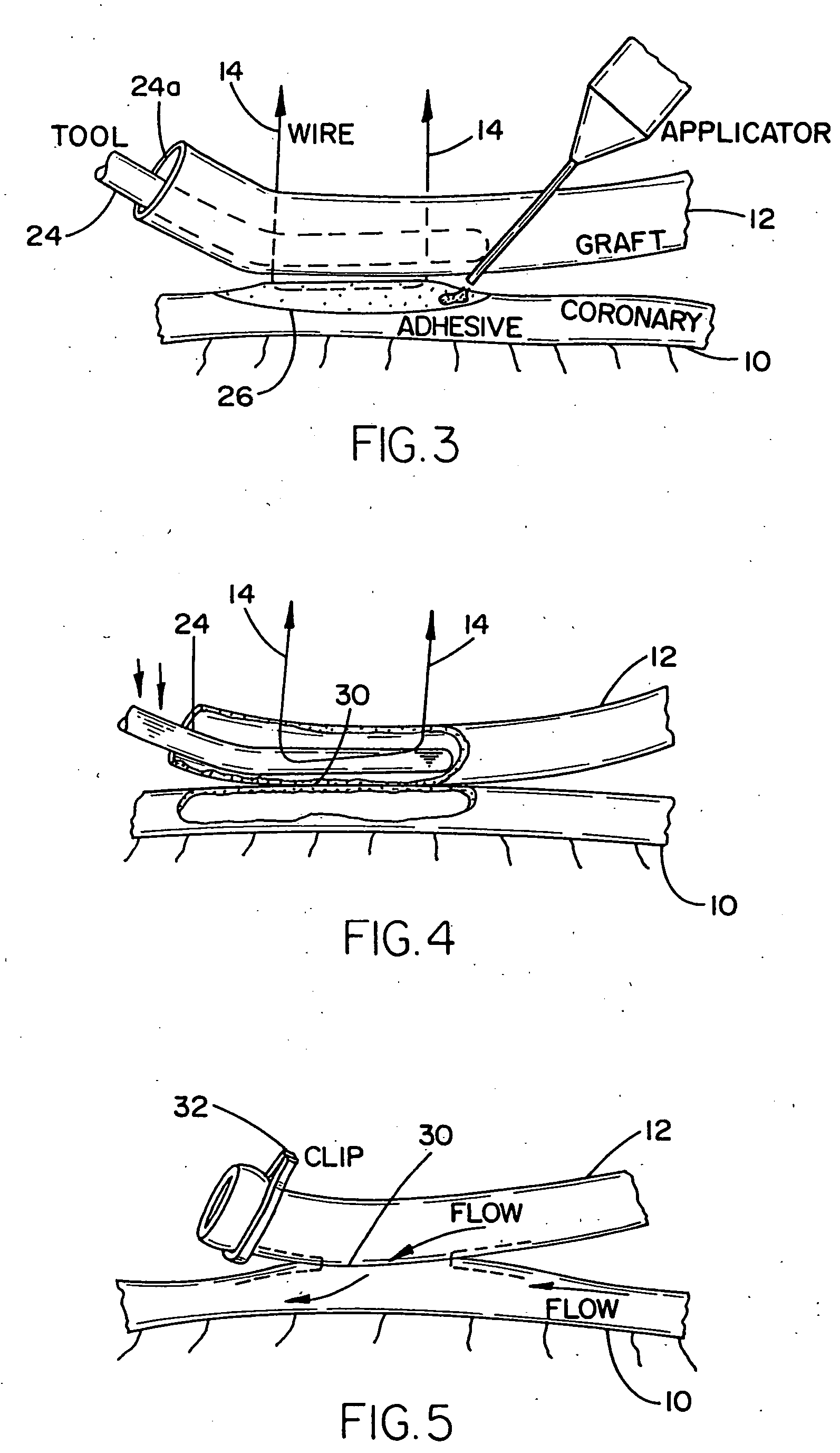
[0051] Referring now to a first embodiment of the anastomosis device and flow passage producing method, as indicated schematically in FIGS. 1a-5 of the drawings, there are represented successive steps in implementing a side-to-side anastomosis between a first body vessel 19, such as a coronary artery, and a second vessel 12 which may be a graft, and wherein the vessels 10,12 are intended to be joined in an edge-to-edge contact rather than intima-to-intima contact. As shown in FIG. 1a of the drawings, a suture wire 14 having a suture needle 16, essentially of curved configuration attached at both ends thereof (only one shown) is inserted into the coronary artery 10 at a first location 18 by puncturing the vessel wall. As indicated in FIG. 1b of the drawings, the suture needle 16 at the leading end of the suture wire 14, is manipulated so as to exit the coronary artery 10 at a second generally axial or longitudinally distant point 20 located therefrom at a distance L, therefrom. The n...


PUM


Abstract

A method for implementing vascular anastomosis in the attachment of a graft vessel to a target vessel such as a coronary artery, and subsequently creating a passageway between the vessels in order to establish fluid flow communication therebetween. Further is to the provision of novel devices which are utilized in implementing the steps of attaching a graft vessel to a target vessel such as a coronary artery through vascular anastomosis, and thereafter creating a fluid flow passageway therebetween.

Description

CROSS REFERENCE TO RELATED APPLICATION [0001] The present application is a continuation application of application Ser. No, 09 / 966,971 filed on Sep. 28, 2001.BACKGROUND OF THE INVENTION [0002] 1. Field of the Invention [0003] The present invention relates to a method for implementing vascular anastomosis in the attachment of a graft vessel to a target vessel such as a coronary artery, and subsequently creating a passageway between the vessels in order to establish fluid flow communication therebetween. The invention is further directed to the provision of novel devices which are utilized in implementing the steps of attaching a graft vessel to a target vessel such as a coronary artery through vascular anastomosis, and thereafter creating a fluid flow passageway therebetween. [0004] The concept of anastomosis in implementing the attachment of target vessels, for instance, such as coronary arteries and other body vessels which are subjected to a fluid flow, such as blood to a graft ve...

Claims


Application Information

Patent Timeline
Patent Type & Authority Applications(United States)
IPC IPC(8): A61B17/00A61B17/04A61B17/06A61B17/11A61B17/32A61B18/14
CPCA61B17/00491A61B17/0469A61B17/11A61B17/32056A61B2017/1139A61B2017/00243A61B2017/06071A61B2017/1107A61B2017/1135A61B18/1442
Inventor SCHULZE, DALE R.
Owner SCHULZE DALE R
Why Eureka
Try Eureka