

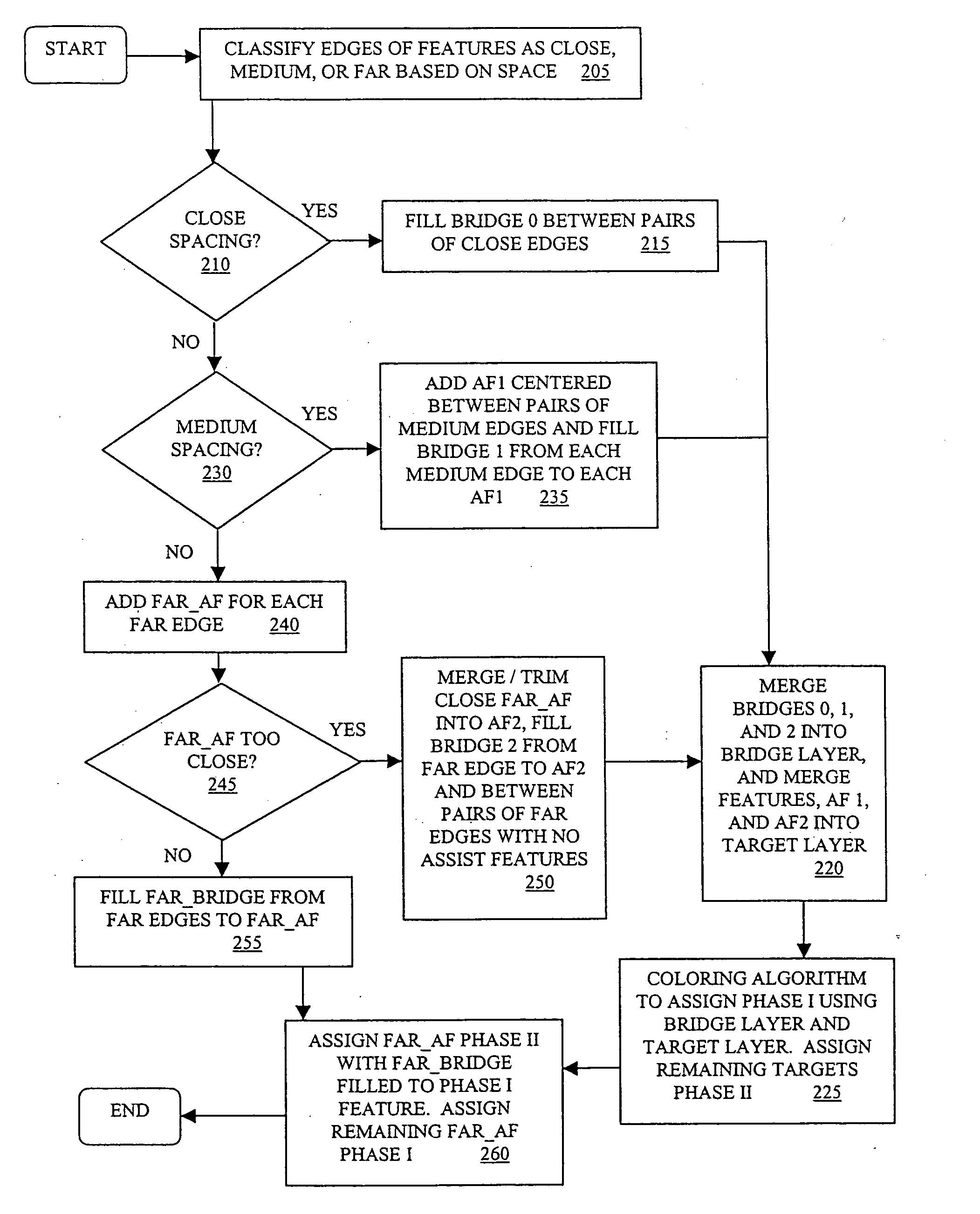
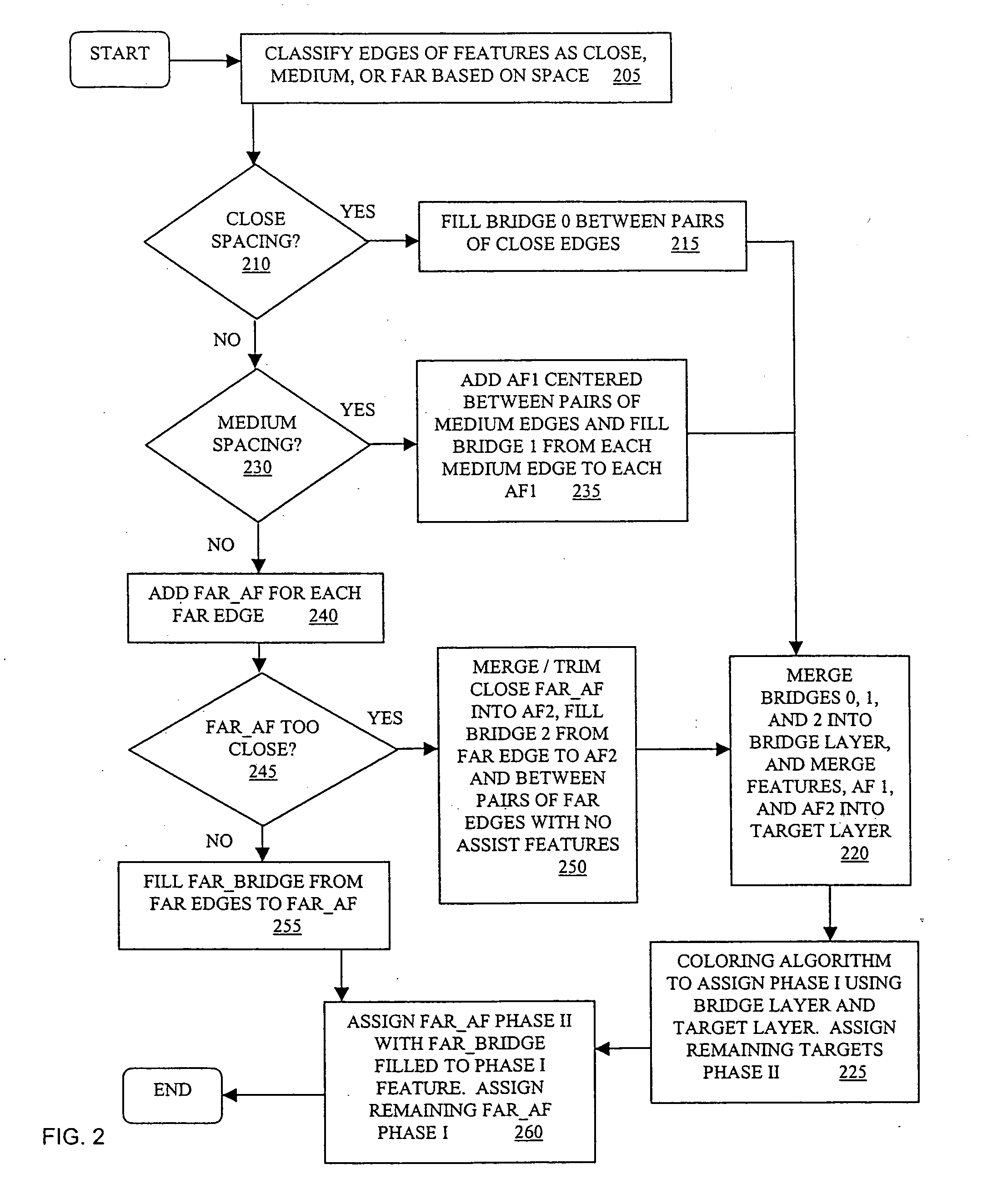
Resolution enhancing technology using phase assignment bridges
a technology of phase assignment and enhancement technology, applied in the field of resolution enhancement technology, can solve the problems of large volume, large complexity, and difficulty in assigning phases, and achieve the effect of reducing the number of phases
- Summary
- Abstract
- Description
- Claims
- Application Information
AI Technical Summary
Benefits of technology
Problems solved by technology
Method used
Image

Examples
Embodiment Construction
[0015] In the following detailed description, numerous specific details are set forth in order to provide a thorough understanding of the present invention. However, those skilled in the art will understand that the present invention may be practiced without these specific details, that the present invention is not limited to the depicted embodiments, and that the present invention may be practiced in a variety of alternate embodiments. In other instances, well known methods, procedures, components, and circuits have not been described in detail.
[0016] Parts of the description will be presented using terminology commonly employed by those skilled in the art to convey the substance of their work to others skilled in the art. Also, parts of the description will be presented in terms of operations performed through the execution of programming instructions. As well understood by those skilled in the art, these operations often take the form of electrical, magnetic, or optical signals ...
PUM
| Property | Measurement | Unit |
|---|---|---|
| separation distance | aaaaa | aaaaa |
| structure | aaaaa | aaaaa |
| length | aaaaa | aaaaa |
Abstract
Description
Claims
Application Information