3D stereo OLED display

a technology of light-emitting diodes and display screens, applied in the field of stereoscopic oled displays, can solve the problems of reducing the ability of multiple users to share and discuss the stereoscopic image, reducing the perceived spatial resolution of the display, and reducing the viewing angle of the display, so as to achieve the effect of effectively producing and altering the handness of circularly polarized light, and large color gamut and viewing angl

Active Publication Date: 2005-07-14
GLOBAL OLED TECH
View PDF64 Cites 47 Cited by
  • Summary
  • Abstract
  • Description
  • Claims
  • Application Information

AI Technical Summary

Benefits of technology

[0012] The present invention has the advantage of providing a stereoscopic OLED display with full spatial resolution, without perceptible artifacts such as flicker and cross talk. The present invention will ideally have a large color gamut and viewing angle as it will effectively produce and alter the handedness of circularly polarized light from a full color display.

Problems solved by technology

Unfortunately, these techniques typically reduce the perceived spatial resolution of the display since half of the columns in the display are used to display an image to either the right or left eye.
These displays also reduce the viewing angle of the display, reducing the ability for multiple users to share and discuss the stereoscopic image that is being shown on the display.
At this relatively low refresh rate, most observers will experience flicker resulting in significant discomfort if the display is used for more than a few minutes within a single viewing session.
Even when the display is refreshed at significantly higher rates, flicker is often visible when the display is large and / or high in luminance.
Further, it is well known that stereoscopic displays formed using linear polarization suffer from a number of artifacts; including narrowing of display's viewing angle and cross-talk (i.e., leakage of light intended for one eye to the other eye) when the linear polarized glasses are turned to an angle other than perpendicular to the columns of the display.
While this display system does not suffer from the same visual artifacts as the system employing switchable polarization that was described by Byatt, the system requires two separate visual displays and additional optics, providing increasing the cost of such a system.
However, as the handedness of the polarization of the light is kept constant during display of stereoscopic imagery, the resolution is reduced due to the fact that each eye can only see half of the columns of the display while viewing stereoscopic imagery.
These polarized displays suffer from one additional constraint due to the fact that the transmission of the polarizing layer is wavelength dependent.
Unfortunately, Kalmanash does not address the problem that each of the circular polarizers can affect polarization over a range of wavelengths and therefore the circular polarizers at the top of the stack may interfere with and, for some wavelengths of the light, will reduce the circular polarization that is introduced by the circular polarizers at the bottom of the stack.
Kalmanash also fails to solve the problem that the active half-wave retarded that is used to rotate the handedness of the circular polarization is also highly wavelength dependent and is therefore incapable of fully changing the handedness of circular polarized light that includes a broad range of wavelengths with multiple peaks as is common within a color imaging device.

Method used


Image

  • 3D stereo OLED display
  • 3D stereo OLED display
  • 3D stereo OLED display

Examples


Embodiment Construction

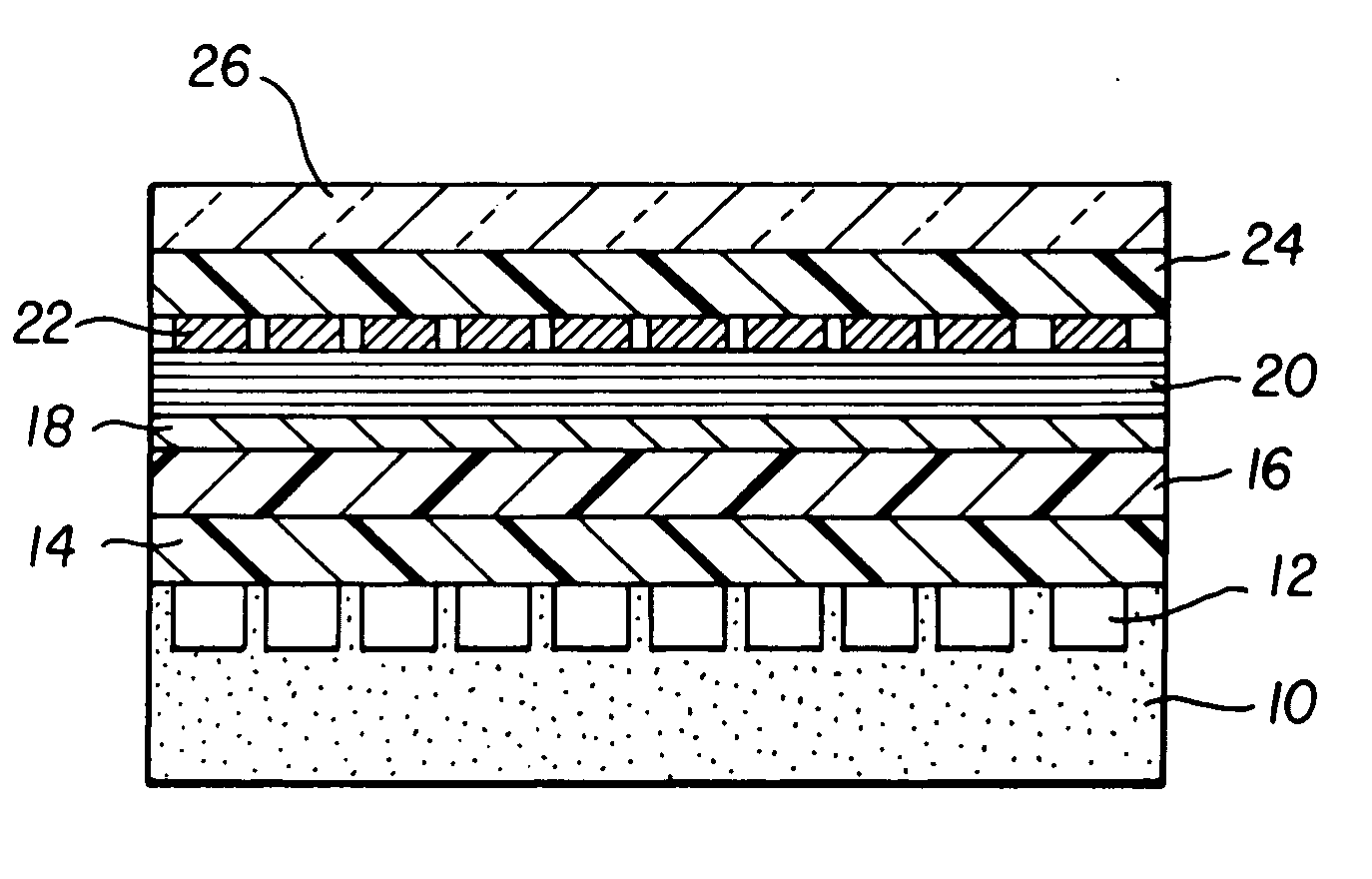
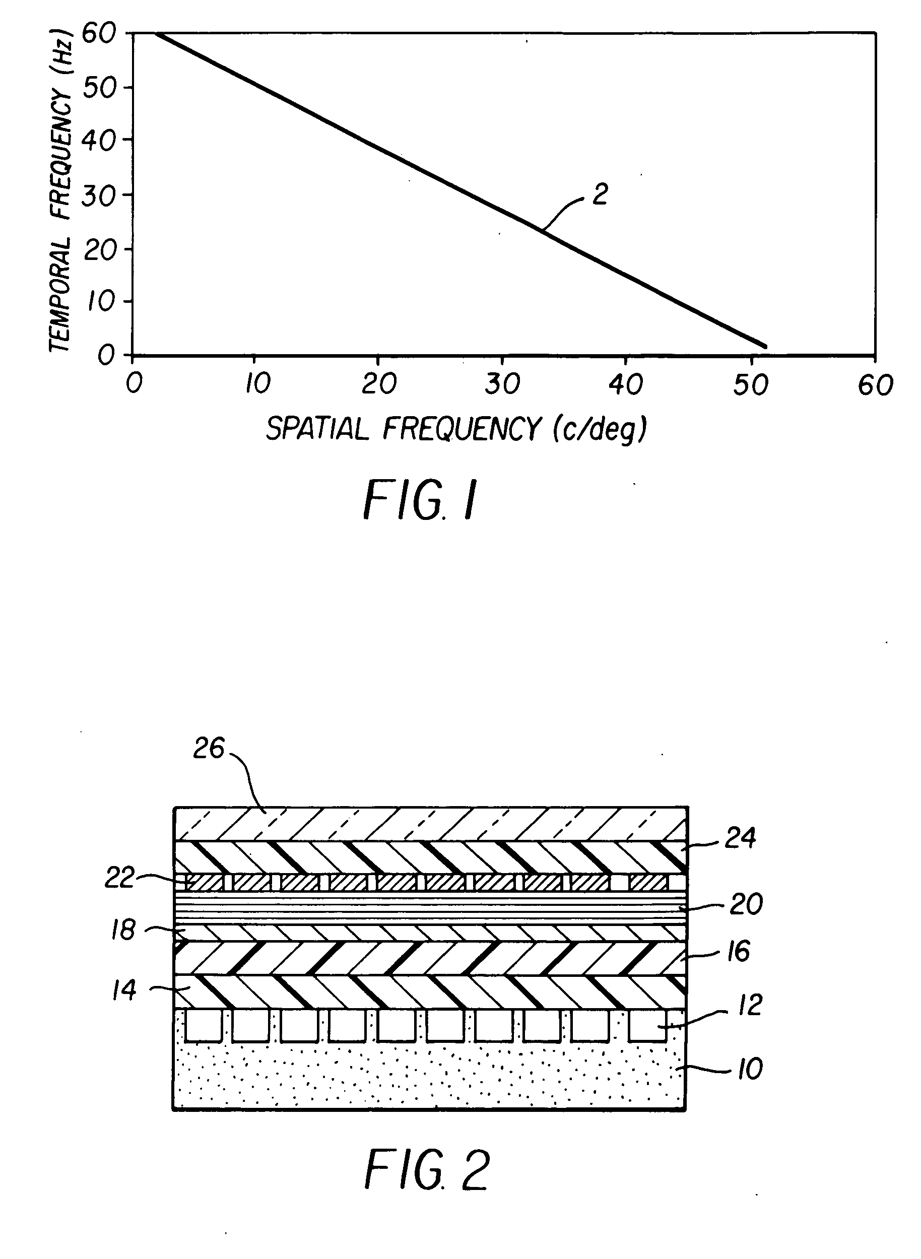
[0022] The invention described herein takes advantage of the fact that while the human visual system is sensitive to patterns that are displayed with high temporal frequency when these patterns are displayed with low spatial frequency, the human visual sensitivity has relatively low sensitivity to patterns that are displayed with high temporal frequencies when the spatial pattern is also high in frequency. FIG. 1 shows a function 2, which is plotted based upon equations provided in Yang and Makous, 1994 (“Spatiotemporal separability in contrast sensitivity”, Vision Research 34(19), pp. 2569-2576) and depicts the temporal frequency at which a typical human observer can detect flicker as a function of the spatial frequency of the pattern that is being displayed. As is well known in the art of visual psychophysics, the temporal frequency that is required to make a flashing light appear without flicker decreases as the spatial frequency of the flickering light increases. For this reason...


PUM


Abstract

A switchable stereoscopic display system, wherein the switchable stereoscopic display system can display two-dimensional and three-dimensional images, includes: an organic light emitting diode (OLED) display device; Electronics that rapidly updates individual OLEDs; and a linearly polarizer for the OLED display device. Additionally, a circular polarizing layer changes light from linearly polarized light to circular polarized light. A polarization layer, on top of the circular polarization layer, switches a polarization direction of emitted light within the OLED display device. Other electronics switches the polarization direction within independent segments of the polarization layer. Refreshed OLEDs are synched with the independent segments of the polarization layer.

Description

FIELD OF THE INVENTION [0001] The invention relates generally to the field of Organic Light Emitting Diode (OLED) Displays, and in particular to Stereoscopic OLED displays. More specifically, the invention relates to an OLED display that provides a stereoscopic image using polarized light. BACKGROUND OF THE INVENTION [0002] Organic Light Emitting Diode (OLED) displays are known in the art. These displays are typically formed from a two-dimensional array of light emitting OLEDs. These solid-state emissive displays typically provide a high contrast ratio for static and dynamic patterns and wide viewing angle, thus providing a very high quality two-dimensional image. [0003] Stereoscopic displays are also known in the art. These displays may be formed using a number of techniques; including barrier screens such as discussed by Montgomery in U.S. Pat. No. 6,459,532 and optical elements such as lenticular lenses as discussed by Tutt et al in U.S. Patent Application 2002 / 0075566. Each of t...

Claims


Application Information

Patent Timeline
Patent Type & Authority Applications(United States)
IPC IPC(8): G02B30/25H01L27/32H01L29/24H01L33/00H01L51/52H04N13/00
CPCG02B27/26H01L27/3211H04N13/0454H01L51/5293H04N13/0434H01L27/3241H04N13/337H04N13/359G02B30/25H10K59/35H10K59/10H10K50/868
Inventor MILLER, MICHAEL E.ASHE, PHILIP R.SPOONHOWER, JOHN P.
Owner GLOBAL OLED TECH
Why Eureka
Try Eureka