Infrared ultrafast laser stainless steel color marking method and system

A stainless steel, infrared super technology, applied in the direction of laser welding equipment, welding equipment, metal processing equipment, etc., can solve the problems of photon unevenness, small color gamut, inconsistent effect, etc., achieve fine energy resolution, vivid color, The effect of improving marking accuracy

Pending Publication Date: 2022-04-26
南京赢羊光子科技有限公司
View PDF0 Cites 0 Cited by
  • Summary
  • Abstract
  • Description
  • Claims
  • Application Information

AI Technical Summary

Problems solved by technology

However, the marking patterns we see in daily marking products are basically black, white and gray, and there are few color patterns
[0003] Some color marking methods use a part of the fiber laser as the core device to mark the color on the stainless steel surface, but they can only print rough color patterns, small color gamut, low resolution, poor precision, and color distortion
There are several main reasons. The first is that the highest limit level of the consistent repeating unit of the core device is at the nanosecond level, resulting in low photon resolution, photon inhomogeneity, poor consistency, etc.
The second is for laser color marking on the surface of stainless steel. The mechanism of the existing marking equipment is developed based on chemical methods. When the laser beam is applied to the surface material of the object to be marked through thermal melting, it generally produces dross. , cracks, heat-affected zone and other adverse effects
The third is to control the process parameters such as laser beam pulse width, power, defocus, filling method, delay parameters, etc., to produce different thicknesses of oxide film marking layers. With different viewing angles, the marking pattern will also change. Different colors are produced, but the overall uniformity is difficult to control, and the inconsistency of the effect is obvious
However, this method has relatively large restrictions on the quality, resolution, uniformity, channels, and even environmental protection requirements of auxiliary materials, and also changes the properties of the stainless steel material body, which is still inconvenient in actual use.

Method used


Image

  • Infrared ultrafast laser stainless steel color marking method and system
  • Infrared ultrafast laser stainless steel color marking method and system
  • Infrared ultrafast laser stainless steel color marking method and system

Examples


Embodiment 1

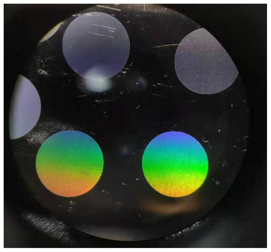
[0071] Embodiment 1: the color marking of the present invention method on stainless steel surface

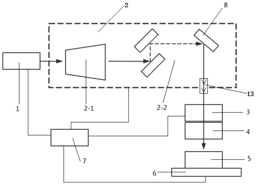
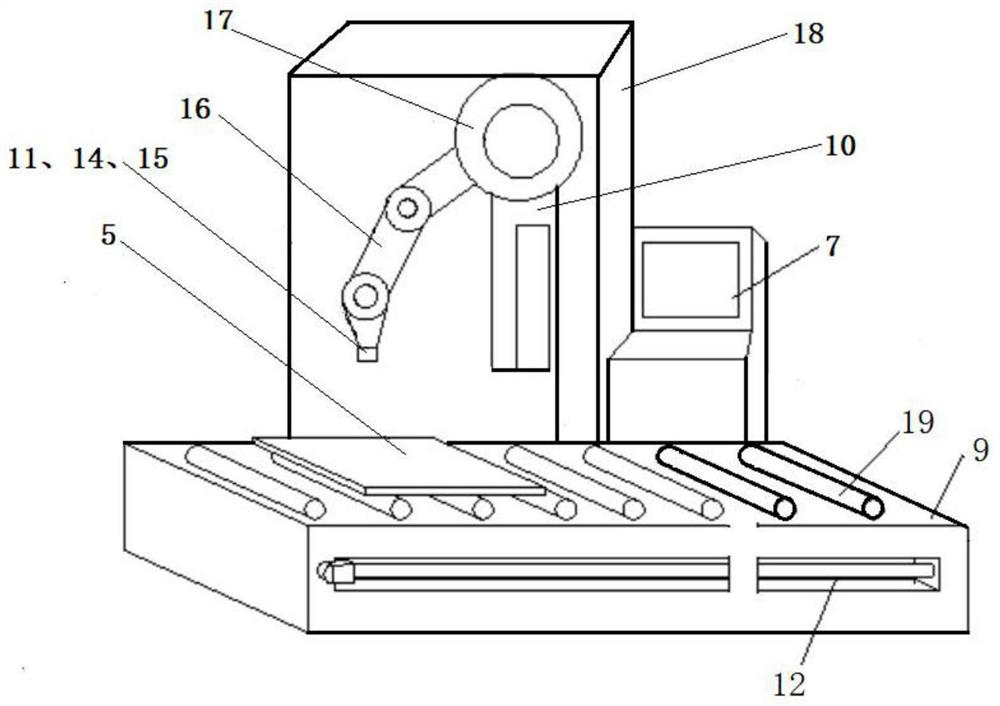
[0072] The laser is connected to the computer installed with the laser marking system software through the data line. The computer inputs the controlled laser power, scanning speed, repetition frequency and other signals to the laser. The infrared ultrafast laser is an all-solid-state picosecond laser. The controller receives the pulse synchronization signal of the laser, and simultaneously controls the laser optical system 10 and the roller conveying mechanism 19 , 12 to complete the laser marking of the stainless steel workpiece 5 .

[0073] The emission frequency of the all-solid-state picosecond laser 1 is 200KHz; the emitted single pulse energy is 10uJ, the single pulse width is 10ps, and the consistency of the single pulse energy is ≤±5%; the duty cycle of the laser pulse marking control signal can be Precise editing, complete the precise editing of the duty cycle through ...


PUM

PropertyMeasurementUnit
frequencyaaaaaaaaaa

Abstract

The invention provides an infrared ultrafast laser stainless steel color marking method and system. The method comprises the steps that stainless steel is placed on a workbench; a laser is arranged on one side of the workbench; the duty ratio of the laser pulse is accurate and editable; ultrafast laser emitted by the laser device is subjected to beam size amplification through the shaping light path, then is input into the galvanometer through the beam transmission light path, and is focused on the surface of a stainless steel workpiece on the workbench after passing through the field lens; and laser marking of patterns on the surface of the stainless steel is completed under the control of the software and hardware controller to form colored marks. According to the method, the stainless steel surface does not need to be subjected to special treatment, the stainless steel surface can be directly marked to form a protective film with high uniformity and good consistency, film reflection is carried out at different angles under natural light, the color effect is achieved, and the color is vivid.

Description

technical field [0001] The invention relates to the technical field of laser marking, in particular to an infrared ultrafast laser stainless steel color marking method and system. Background technique [0002] In recent years, laser marking has replaced traditional marking methods in many fields and has become a conventional processing method, and even formed a new industrial standard. There are more and more markets in the stainless steel application field. However, the marking patterns we see in daily marking products are basically black, white and gray, and there are few colored patterns. [0003] Some color marking methods use a part of the fiber laser as the core device to mark the color on the stainless steel surface, but they can only print rough color patterns, small color gamut, low resolution, poor precision, and color distortion. There are several main reasons. The first is that the highest limit level of the consistent repeating unit of the core device is at the...

Claims


Application Information

Patent Timeline
Patent Type & Authority Applications(China)
IPC IPC(8): B23K26/362B23K26/70
CPCB23K26/362B23K26/702B23K2103/05
Inventor 不公告发明人
Owner 南京赢羊光子科技有限公司
Why Eureka
Try Eureka