Avalanche transceiver

Inactive Publication Date: 2005-07-14
KASHUBA DOUGLAS
View PDF9 Cites 23 Cited by
  • Summary
  • Abstract
  • Description
  • Claims
  • Application Information

AI Technical Summary

Benefits of technology

[0034] The present invention comprises a transmitter capable of transmitting a constant wave radio signal at a predetermined frequency. The system provides a means for users to select different transmission intervals. When each member of a group selects a different transmission interval, the occurence of collisions in the event of multipl

Problems solved by technology

This crossed dual-antenna implementation does break down, however, in close proximity to the burial.
This causes the 90-degree summing rule to deteriorate and, consequently, false left and right indications may occur.
However, the antenna(s) contribute considerably to the size and weight of the transceiver unit.
A collision occurs when the signals from two or more transmitting beacons combine in such a way as to interfere with each other.
Any measurements taken during collisions are unrealiable.
If the two signals are exactly the same frequency and also 180 degrees out of phase, the peaks and valleys of the signals will combine to wipe out both signals and the receiver w

Method used


Image

  • Avalanche transceiver
  • Avalanche transceiver
  • Avalanche transceiver

Examples


Embodiment Construction

)

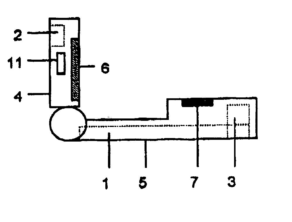
[0043] As illustrated in FIG. 4 and FIG. 5, the present invention comprises a receiver with three mutually orthogonal receiving antennas 1, 2 and 3. Antenna 1 is oriented in the forward / backward direction of the housing. Antenna 2 is oriented in the left / right direction while antenna 3 is oriented in the up / down direction. In the preferred embodiment, the antennas are tuned-coil antennas receiving signals at 457 kHz. In another embodiment, the antennas are tuned to receive at 398 kHz for snowmobilers.

[0044] In the present invention, antenna 1 is the largest antenna. Antennas 2 and 3 are smaller in size and are located away from antenna 1. By spatially isolating antennas 2 and 3 away from antenna 1, each antenna has a higher sensitivity and, consequently, a higher range of operation. FIG. 4 and FIG. 5 show antenna 2 located in the flip lid 4 while antennas 1 and 3 are located in the main housing 5. While this is the preferred embodiment, other embodiments with different antenna loc...


PUM


Abstract

An improved battery-powered device and system for avalanche transceiver rescue. The device comprises a transmitter, a receiver, microcontroller firmware system, graphic display, audio speaker and input switches residing in a single portable housing with a flip lid. When the flip lid is closed, the system transmits a radio frequency signal at a predetermined interval. When the flip lid is opened, the system deactivates the transmitter and activates the receiver. The receiver comprises three mutually orthogonal tuned-coil antennas. The system digitally processes the received signal strength and polarity of the signal from one or more of the antennas to guide a user to a transmitting beacon. The antennas are spatially isolated permitting the use of higher-sensitivity antennas. The system digitally controls the sensitivity of each antenna enabling scans for signals based on a specified proximity range to the exclusion of other proximity ranges. The system also displays an indication when a degraded signal is received as a result of signal collision from multiple beacons.

Description

BACKGROUND OF THE INVENTION [0001] 1. Field of the Invention [0002] The present invention is directed to rescuing victims accidentally buried in an avalanche. Each member of a group wears a battery-powered transceiver device in transmit mode which intermittently broadcasts a radio frequency signal at a predetermined frequency. In the event of accidental burial in snow, a non-buried member of the group changes their transceiver to operate in receive mode. Using signal strength, distance and / or orientation information from the transceiver, the searcher locates the position of the buried transmitted signal. [0003] 2. Description of the Prior Art [0004] The state of the prior art is represented by two types of avalanche transceivers: (a) single-antenna analog transceivers and (b) dual-antenna digital transceivers. The apparatus described under U.S. Pat. No. 6,246,863 of Kampel is representative of the first type (analog). The apparatus described under U.S. Pat. No. 6,484,021 of Hereford...

Claims


Application Information

Patent Timeline
IPC IPC(8): A62B33/00A63B29/02G01S3/30
CPCA62B33/00G01S3/30A63B29/021
Inventor KASHUBA, DOUGLASPACHAL, EDWARD G.PACHAL, CYNTHIA G.
Owner KASHUBA DOUGLAS
Why Eureka
Try Eureka