Backlight control circuit in portable device

Inactive Publication Date: 2005-07-14
SAMSUNG ELECTRONICS CO LTD
View PDF5 Cites 36 Cited by
  • Summary
  • Abstract
  • Description
  • Claims
  • Application Information

AI Technical Summary

Benefits of technology

[0008] Accordingly, the present invention has been made to solve the above-mentioned problems occurring in the prior art, and a first object of the present invention is to pr

Problems solved by technology

In this case, since the illuminating device constantly maintains a turned-on state due to continuous key inputs, current is continuously consumed and a volume of thermal emission of the illuminating device increases.
For this

Method used


Image

  • Backlight control circuit in portable device
  • Backlight control circuit in portable device
  • Backlight control circuit in portable device

Examples


first embodiment

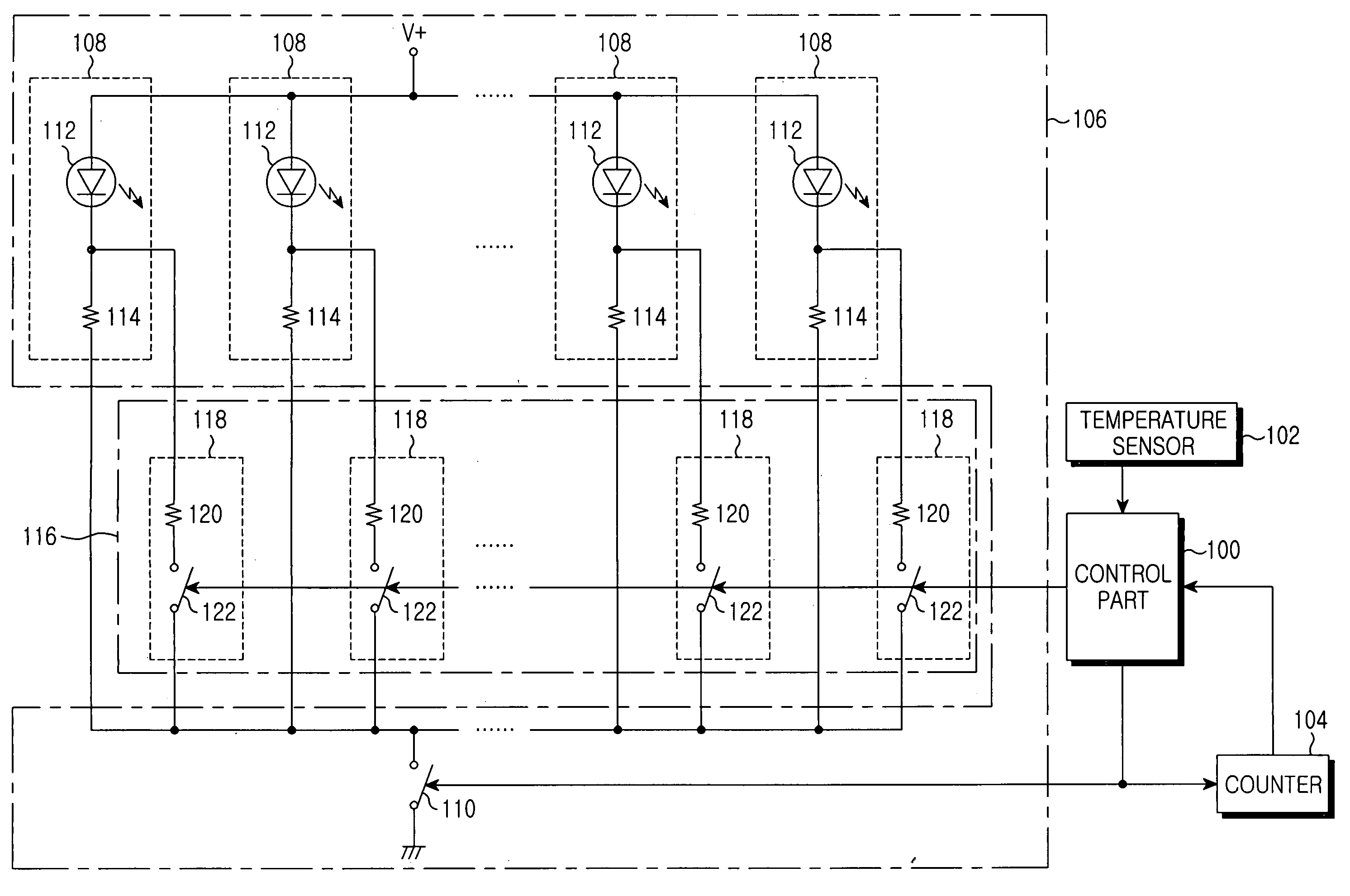
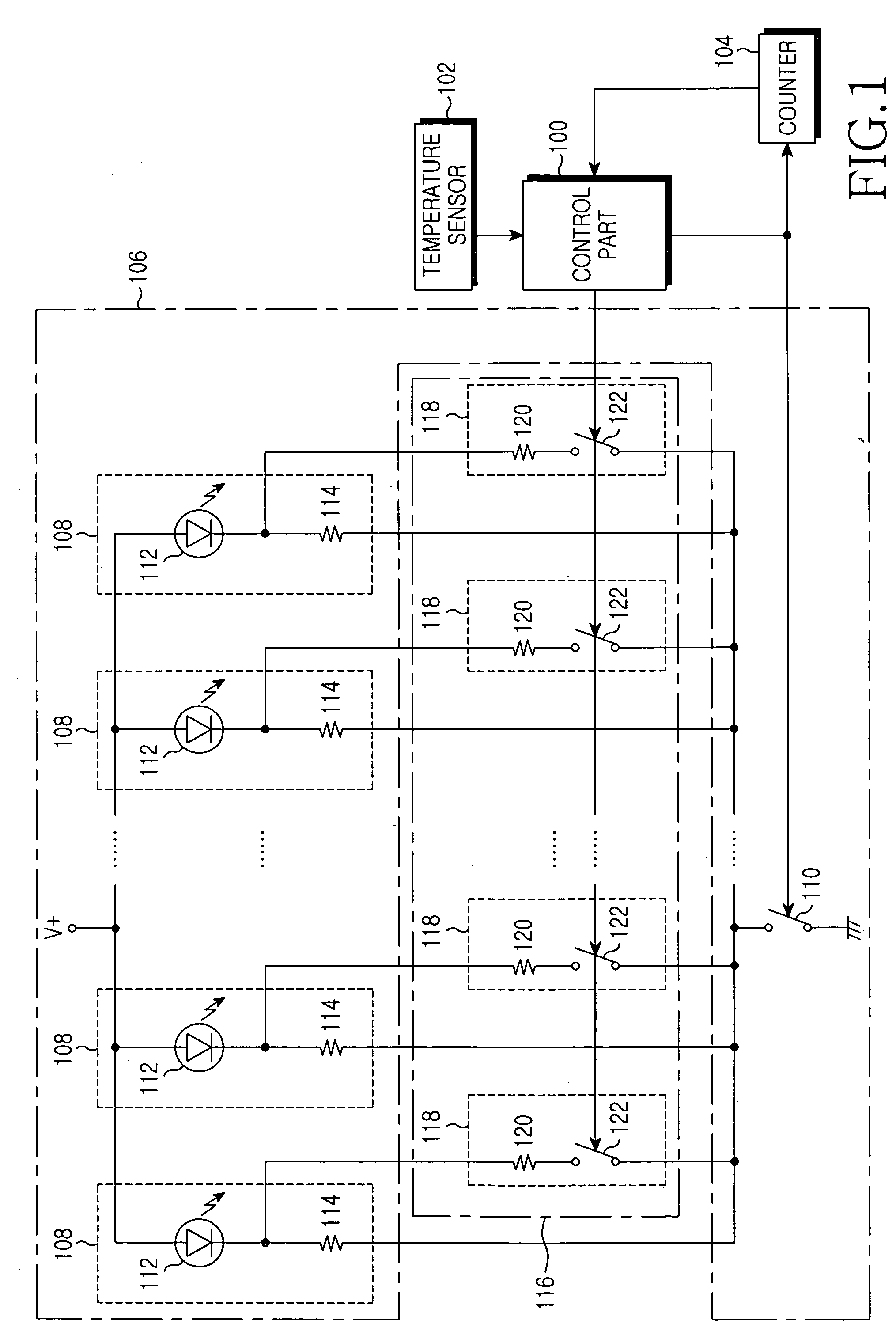
[0018] The backlight control circuit according to the present invention is shown in FIG. 1, and includes a temperature sensor 102, a counter 104, and a current controlling part 116 in order to control backlight through a conventional backlight circuit 106 controlling on / off switching of illuminating devices by a control part 100. The backlight circuit 106 employs light emitting diodes (LEDs) 112 as illuminating devices for illuminating liquid crystal displays (LCDs), key buttons and so forth included in portable devices using the backlight control circuit shown in FIG. 1. Plural sets of the LEDs 112 and resistors 114 are connected to each other in series between a voltage source terminal (V+) and a ground by interposing a backlight controlling switch 110 therebetween. The backlight controlling switch 110 is used for turning on / off the LEDs 112 and is switched under the control of the control part 100.

[0019] The control part 100 turns on the backlight controlling switch 110 when a ba...

second embodiment

[0027]FIG. 3 is a view showing a backlight control circuit according to the present invention. In contrast to the backlight control circuit shown in FIG. 1, which individually controls current flowing through the LEDs 112 by connecting each LED 112 to each current controlling switch 122, the backlight control circuit according to the present embodiment applies electric power to the LEDs 112 through a current controlling part 124. Accordingly, the control part 100, the temperature sensor 102, the counter 104, and the backlight circuit 106 have structures identical to the structures shown in FIG. 1. The current controlling part 124 includes a resistor 126 and a current switch 128 connected to each other in parallel between the voltage source (V+) and the LEDs 112. The current controlling switch 128 is turned on or off by the control part 100 similar to the current controlling switches 122 described with reference to FIG. 1. If the current controlling switch 128 is turned on, the elect...


PUM


Abstract

Disclosed is a backlight control circuit capable of decreasing current applied to an illuminating device or turning off a portion of illuminating devices if an illuminating time exceeds a predetermined reference time when the illuminating device is in a turned-on state, or a thermal emission temperature of the illuminating device is higher than a predetermined reference temperature. Accordingly, it is possible to reduce current consumption and thermal emission of the illuminating device resulting from continuous turn-on states of the illuminating device while using a backlight function.

Description

PRIORITY [0001] This application claims priority to an application entitled “Backlight Control Circuit In Portable Device” filed in the Korean Intellectual Property Office on Dec. 18, 2003 and assigned Serial No. 2003-93185, the contents of which are hereby incorporated by reference. BACKGROUND OF THE INVENTION [0002] 1. Field of the Invention [0003] The present invention relates to a portable device, and more particularly to a circuit allowing an illuminating device to provide backlight for the portable device. [0004] 2. Description of the Related Art [0005] In general, a liquid crystal display (LCD) is widely used as a display unit of portable devices such as a mobile communication terminal, a smart phone, and so forth. The LCD itself does not emit light, unlike a cathode ray tube (CRT), an electroluminescence element (EL), and so forth. Therefore, additional illumination is required for an LCD screen in such a manner to illuminate images are visually displayed on the LCD screen. ...

Claims


Application Information

Patent Timeline
IPC IPC(8): G09G3/36G02F1/133
CPCG09G3/3406H05B33/0854G09G2330/021G09G2320/041H05B45/18G02F1/133
Inventor SEO, JAE-MIN
Owner SAMSUNG ELECTRONICS CO LTD
Why Eureka
Try Eureka