Projection screen and projection system comprising the same

a projection screen and projection system technology, applied in the field of projection systems, can solve the problems of difficult for such a conventional projection screen to show good image display performance, difficult for the conventional projection screen to provide good image display, and small differences in brightness between white and black, so as to achieve double-enhanced image contrast, excellent color display, and low brightness of the dark-indication part

Inactive Publication Date: 2005-07-14
DAI NIPPON PRINTING CO LTD
View PDF3 Cites 14 Cited by
  • Summary
  • Abstract
  • Description
  • Claims
  • Application Information

AI Technical Summary

Benefits of technology

[0034] Furthermore, in the present invention, the two or more selective reflection layers in the projected-image-receiving layer are preferably a selective reflection layer having a reflection wave range with a center wavelength of 430 to 460 nm, a selective reflection layer having a reflection wave range with a center wavelength of 540 to 570 nm, and a selective reflection layer having a reflection wave range with a center wavelength of 580 to 620 nm, provided that light enters the projected-image-receiving layer vertically to it. By so making the selective reflection layers, the projected-image-receiving layer can reflect imaging light (light in the wave ranges for red (R), green (G) and blue (B) colors, the three primary colors of light) projected from a projector such as a liquid crystal projector. There can thus be obtained a projection screen capable of attaining excellent color display.
[0035] In the present invention, the specific polarized-light component which the projected-image-receiving layer selectively reflects is either right- or left-handed circularly polarized light. In this case, the projected-image-receiving layer selectively reflects only a specific polarized-light component (e.g., right-handed circularly polarized light) owing to its function of selectively reflecting light (the polarized-light-separating property). It is, therefore, possible to make the projected-image-receiving layer reflect only approximately 50% of unpolarized environmental light, such as sunlight and light from lighting fixtures, incident on the projected-image-receiving layer. For this reason, while maintaining the brightness of the light-indication part such as a white-indication part, it is possible to lower the brightness of the dark-indication part such as a black-indication part to nearly half, thereby obtaining nearly twice-enhanced image contrast. In this case, if the imaging light to be projected is made to mainly contain a polarized-light component that is identical with the one which the projected-image-receiving layer selectively reflects (e.g., right-handed circularly polarized light), the projected-image-receiving layer can reflect nearly 100% of the imaging light projected, that is, the projected-image-receiving layer can efficiently reflect the imaging light. Even a projector that emits linearly polarized light, such as a liquid crystal projector, can be used, regardless of the direction of linear polarization, for projecting imaging light on the projection screen, if a retardation layer or the like for converting linearly polarized light into circularly polarized light is used.
[0036] Furthermore, in the present invention, the specific polarized-light component which the projected-image-receiving layer selectively reflects may also be a linearly polarized light of one vibration direction. In this case, the specific polarized-light component which the projected-image-receiving layer selectively reflects is either P- or S-polarized light, and the projected-image-receiving layer selectively reflects only a specific polarized-light component (e.g., P-polarized light) owing to its function of selectively reflecting light (polarized-light-separating property). It is, therefore, possible to make the projected-image-receiving layer reflect only approximately 50% of unpolarized environmental light, such as sunlight and light from lighting fixtures, incident on the projected-image-receiving layer. For this reason, while maintaining the brightnes

Problems solved by technology

However, it is difficult for such a conventional projection screen to show good image display performance under bright environmental light because it reflects not only imaging light but also environmental light such as sunlight and light from lighting fixtures.
However, since the above-described conventional projection screen reflects both imaging light and environmental light such as sunlight and light from lighting fixtures without distinction, both the white- and black-indication parts get lighter, and differences in brightness between white and black become small.
For this reason, it has not been easy for the conventional projection screen to provide good image display unless the influence of environmental light, such as sunlight and light from lighting fixtures, on the projection screen is suppressed by using a means for shading a room, or by placing the projection screen in a dark environment.
However, holograms have wavelength selectivity but no polarization selectivity, so that the projection screens using holograms can display images only with limited sharpness

Method used


Image

  • Projection screen and projection system comprising the same
  • Projection screen and projection system comprising the same
  • Projection screen and projection system comprising the same

Examples


first embodiment

(1) First Embodiment

[0056] The first embodiment of the projected-image-receiving layer 2 will be firstly described. As described above, this embodiment is that the projected-image-receiving layer 2 includes, in addition to the two or more selective reflection layers having the function of selectively reflecting a specific polarized-light component, a diffusing layer having the function of diffusing the specific polarized-light component. Namely, in the projected-image-receiving layer 2 according to the first embodiment, the selective reflection layers act only to reflect a specific polarized-light component, while the diffusing layer diffuses the specific polarized-light component.

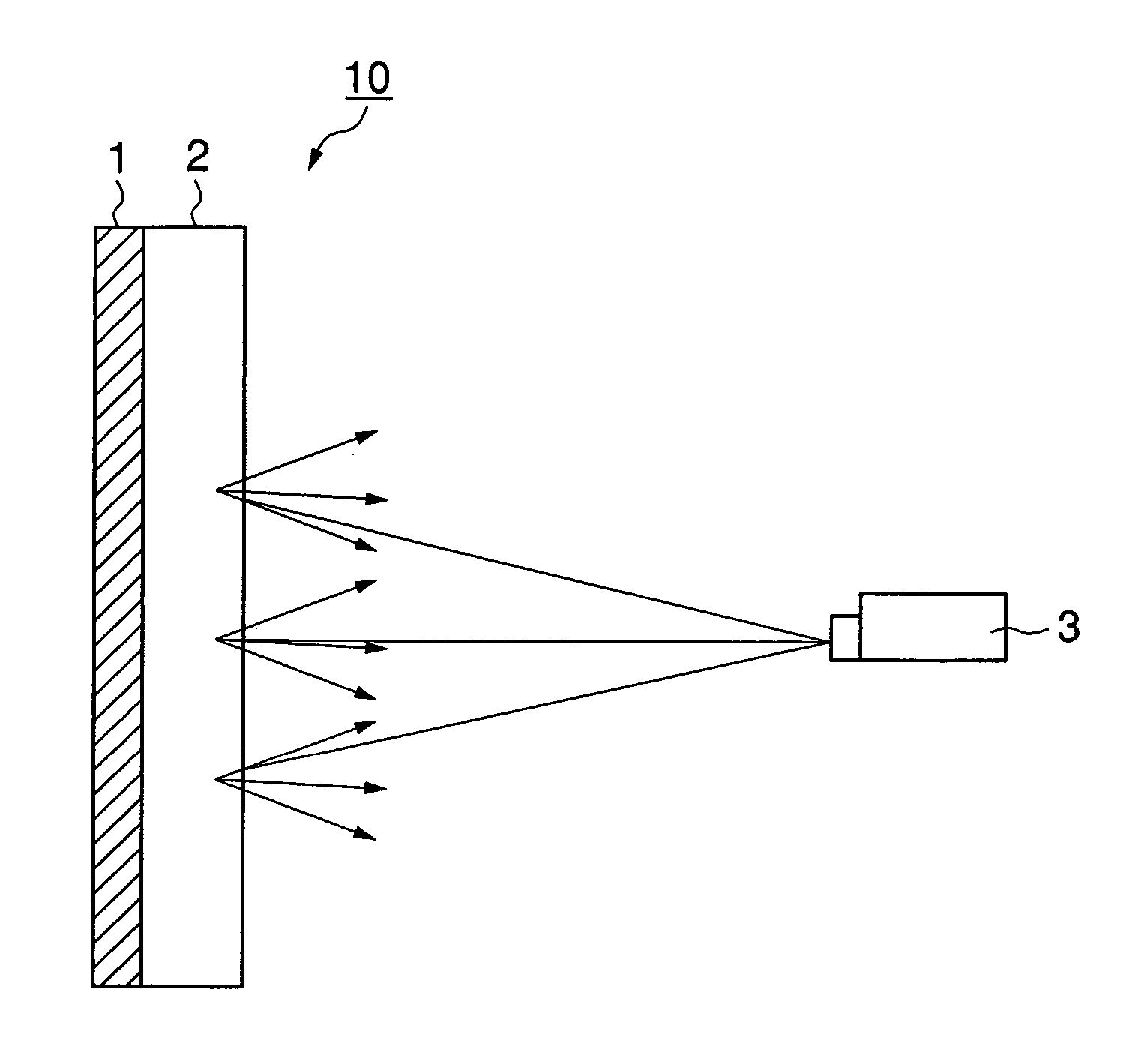
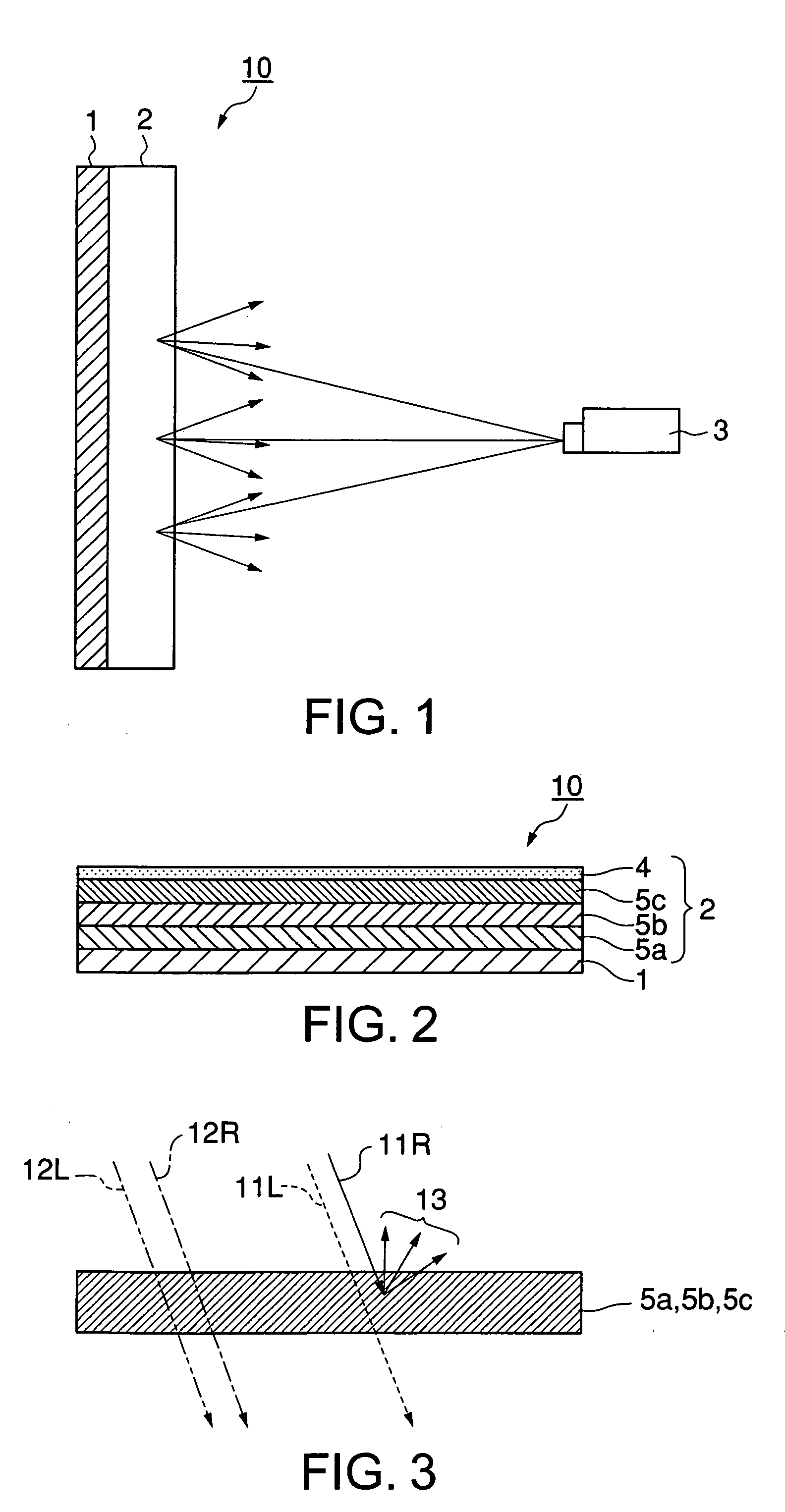
[0057] For example, the projected-image-receiving layer 2 according to the first embodiment includes, as shown in FIG. 2, a plurality of selective reflection layers 5a, 5b and 5c and a diffusing layer 4 formed on these selective reflection layers 5a, 5b and 5c. Of these selective reflection layers 5a, 5b ...

second embodiment

(2) Second Embodiment

[0079] The second embodiment of the projected-image-receiving layer 2 will be described below. As mentioned above, the second embodiment of the projected-image-receiving layer 2 is that each selective reflection layer constituting the projected-image-receiving layer 2 has both the function of selectively reflecting a specific polarized-light component and the function of diffusing the specific polarized-light component.

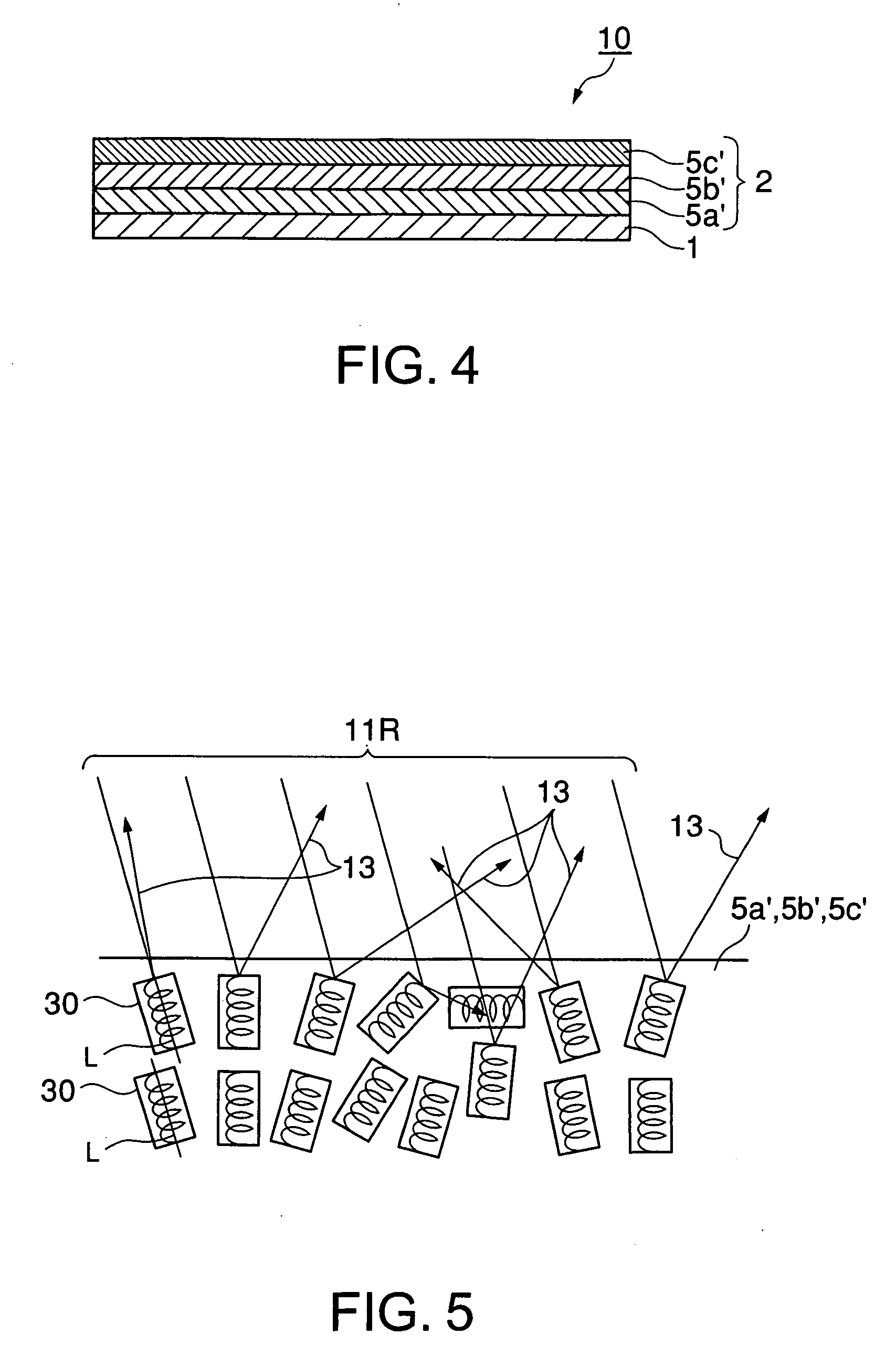
[0080] Such a projected-image-receiving layer 2 according to the second embodiment includes a laminate of a plurality of selective reflection layers 5a′, 5b′ and 5c′ having both the function of selectively reflecting a specific polarized-light component and the function of diffusing the specific polarized-light component, as shown in FIG. 4, for example. In this case, the selective reflection layer 5a′ having a reflection wave range covering the shortest wavelength side is provided on the substrate 1, the selective reflection layer5b′ having a re...

examples

[0149] A specific example of the above-described embodiments will now be given below.


PUM


Abstract

A projection screen for displaying an image by reflecting imaging light projected from a projector, including a substrate and a projected-image-receiving layer formed on the substrate. The projected-image-receiving layer has the function of selectively reflecting a specific polarized-light component and the function of diffusing the specific polarized-light component. Further, the projected-image-receiving layer includes two or more selective reflection layers having different reflection wave ranges, and, of these selective reflection layers, the selective reflection layer having a reflection wave range covering the shorter wavelength side is situated apart from the observation side as compared with the selective reflection layer having a reflection wave range covering the longer wavelength side.

Description

BACKGROUND OF THE INVENTION [0001] 1. Field of the Invention [0002] The present invention relates to a projection system in which imaging light emitted from a projector is projected on a projection screen to produce thereon an image. More particularly, the present invention relates to a projection screen capable of sharply displaying an image and of providing high image visibility, and to a projection system comprising such a projection screen. [0003] 2. Background Art [0004] Conventional projection systems for business and home uses are as follows: imaging light such as an image emitted from a projector is projected on a projection screen, and viewers observe the light reflected from the projection screen as an image. In such conventional projection systems, a projection screen comprising a transparent medium in which transparent or semitransparent, porous, finely divided particles are dispersed and a reflecting member provided at the rear of this transparent medium is used, for ex...

Claims


Application Information

Patent Timeline
IPC IPC(8): G03B21/60
CPCG03B21/60
Inventor UMEYA, MASANORI
Owner DAI NIPPON PRINTING CO LTD
Why Eureka
Try Eureka