
Display and display mounting apparatus

a technology for mounting apparatuses and displays, applied in the field of display, can solve the problems of difficult connection of cables, complicated structure of electrical apparatuses, etc., and achieve the effect of convenient adjustment and easy connection

Active Publication Date: 2005-07-14
SAMSUNG ELECTRONICS CO LTD
View PDF9 Cites 117 Cited by
  • Summary
  • Abstract
  • Description
  • Claims
  • Application Information

AI Technical Summary

Benefits of technology

The present invention provides a display with a screen that can be easily adjusted to a desired view angle and has a cable port for easy connection of a cable to the rear of the display. The display can be rotated between a first tilted position and a second tilted position. The display also includes a main bracket and a safety supporter to secure the cable work space and safely maintain the display in the second tilted position. The technical effects of the invention include easy adjustment of view angle, secure cable connection, and improved safety for the display.

Problems solved by technology

However, in the conventional display, since the mounting apparatus includes the damping unit having the gas damper and the wire, and the locking unit, etc., a structure thereof becomes complicated.
Therefore, in the state that the display is mounted to the mounting wall as shown in FIG. 7, there arises a problem in that it is difficult to connect the cable 195 to the cable port provided in the back lower portion of the display main body 101.

Method used


Image

  • Display and display mounting apparatus
  • Display and display mounting apparatus
  • Display and display mounting apparatus

Examples


Embodiment Construction

[0033] Reference will now be made in detail to the present preferred embodiments of the present general inventive concept, examples of which are illustrated in the accompanying drawings, wherein like reference numerals refer to the like elements throughout. The embodiments are described below in order to explain the present general inventive concept by referring to the figures.

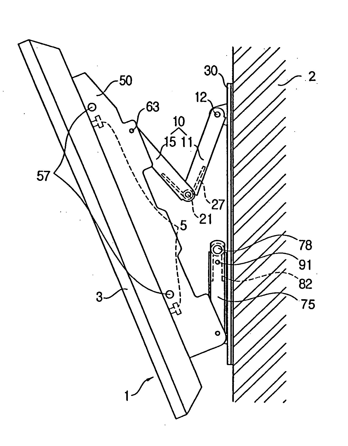
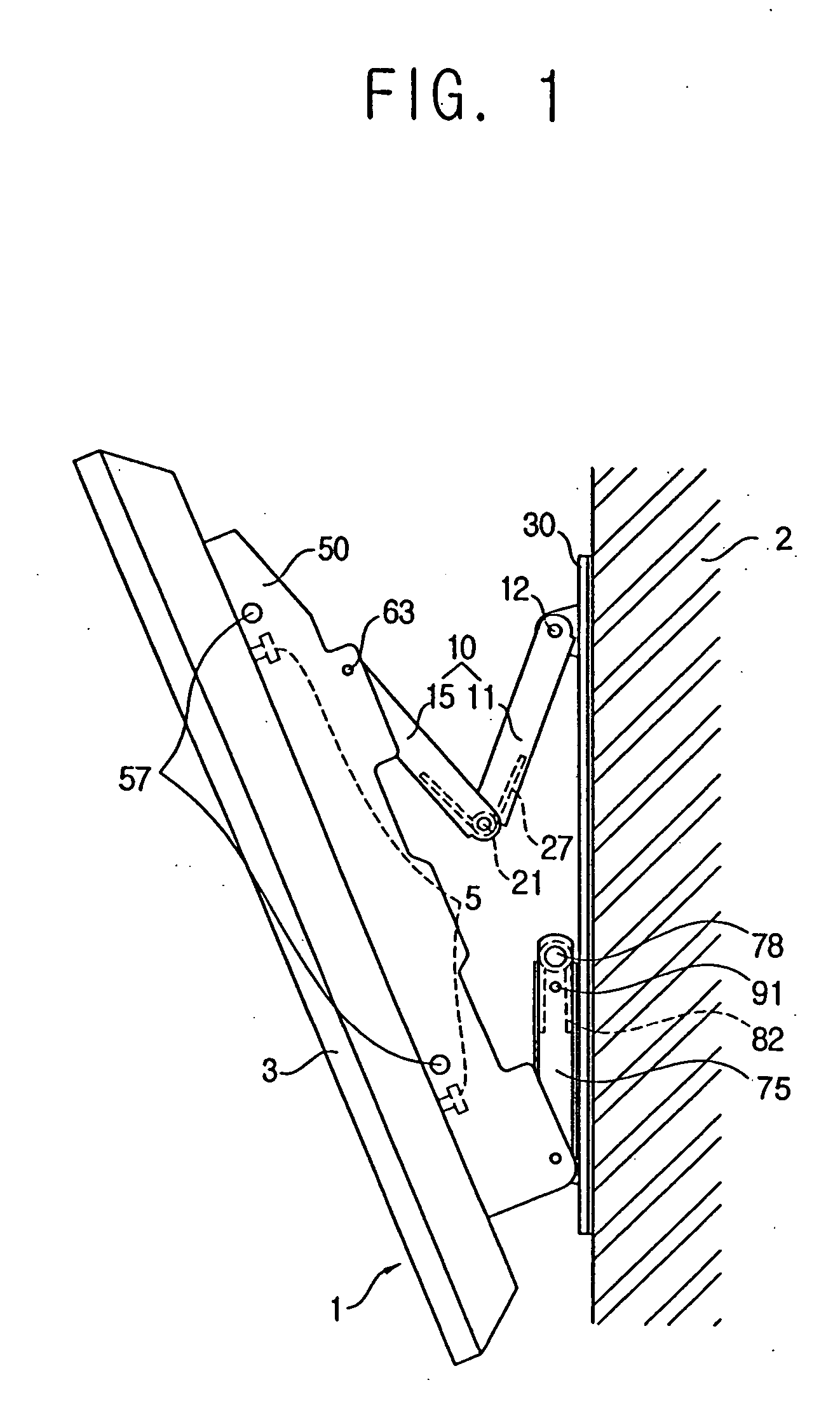
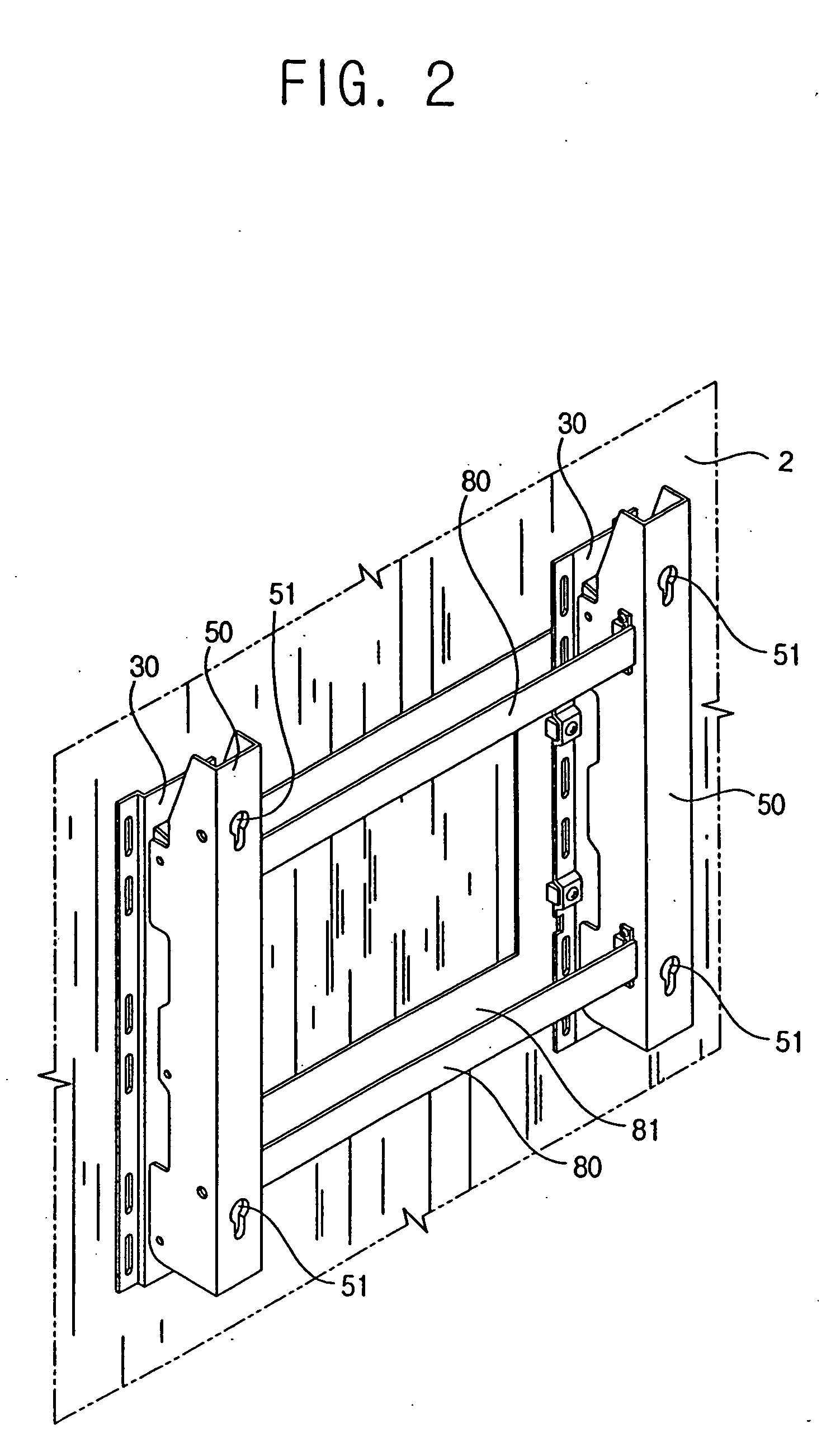
[0034]FIG. 1 is a lateral perspective view of a display at in a first tilted position according to an embodiment of the present general inventive concept, and FIGS. 2 through 4 are a perspective view, an exploded perspective view, and a partial exploded perspective view of a display mounting apparatus in the display of FIG. 1, respectively. As shown in FIG. 1, the display may include a display main body 1 having a screen 3, and the display mounting apparatus to tiltably mount the display main body 1 onto a predetermined seating surface. The display mounting apparatus may include a main bracket 50 to support t...


PUM


Abstract

A display with a display main body having a screen includes an upper link assembly which includes an upper first link having a first end rotatably coupled with a mounting wall, and an upper second link having a first end rotatably coupled with the display main body and a second end rotatably coupled with a second end of the upper first link and connects an upper rear portion of the display main body to the mounting wall, and a lower link assembly which includes a lower first link having a first end rotatably coupled with the mounting wall, and a lower second link having a first end rotatably coupled with the display main body and a second end rotatably coupled with a second end of the lower first link and connects a lower rear portion of the display main body to the mounting wall. The display main body is rotatable between a first tilted position that an upper portion thereof is apart from the mounting wall while a lower portion is in contact with the mounting wall, and a second tilted position that the upper portion is in contact with the mounting wall while the lower portion is apart from the mounting wall.

Description

CROSS-REFERENCE TO RELATED APPLICATIONS [0001] This application claims the benefit of Korean Patent Application No. 2004-01491, filed on Jan. 9, 2004, in the Korean Intellectual Property Office, the disclosure of which is incorporated herein by reference. BACKGROUND OF THE INVENTION [0002] 1. Field of the Invention [0003] The present general inventive concept relates to a display, and more particularly, to a display having an improved structure to mount a display main body onto a mounting wall. [0004] 2. Description of the Related Art [0005] Generally, a display includes a display main body having a screen, and a display mounting apparatus for mounting the display main body onto a predetermined seating place. [0006] Recently, the display main body employs a display device, such as a liquid crystal display (LCD), a plasma display panel (PDP), etc., for a screen, so that an area of the screen becomes larger and a thickness thereof becomes relatively thin, thereby allowing the display ...

Claims


Application Information

Patent Timeline
Patent Type & Authority Applications(United States)
IPC IPC(8): F16M11/10H04N5/655F16M13/02G06F1/16
CPCF16M11/10F16M2200/041F16M13/02F16M11/2092Y10S248/917Y10S248/92B66B13/24B66B11/06
Inventor SHIN, YONG-HA
Owner SAMSUNG ELECTRONICS CO LTD
Learn More