Radio base station with multiple radio frequency heads

Inactive Publication Date: 2005-07-14
RPX CORP
View PDF6 Cites 51 Cited by
  • Summary
  • Abstract
  • Description
  • Claims
  • Application Information

AI Technical Summary

Benefits of technology

[0009] The introduction of a bi-directional fiber ring enables the use of distributed radio equipment, supports macro and pico-cell applications and leads to simpler and

Problems solved by technology

Moreover, the use of longer interconnections would lead to problems with different propagation delays between baseband unit and the several RF heads.
The specification assumes

Method used


Image

  • Radio base station with multiple radio frequency heads
  • Radio base station with multiple radio frequency heads
  • Radio base station with multiple radio frequency heads

Examples


Embodiment Construction

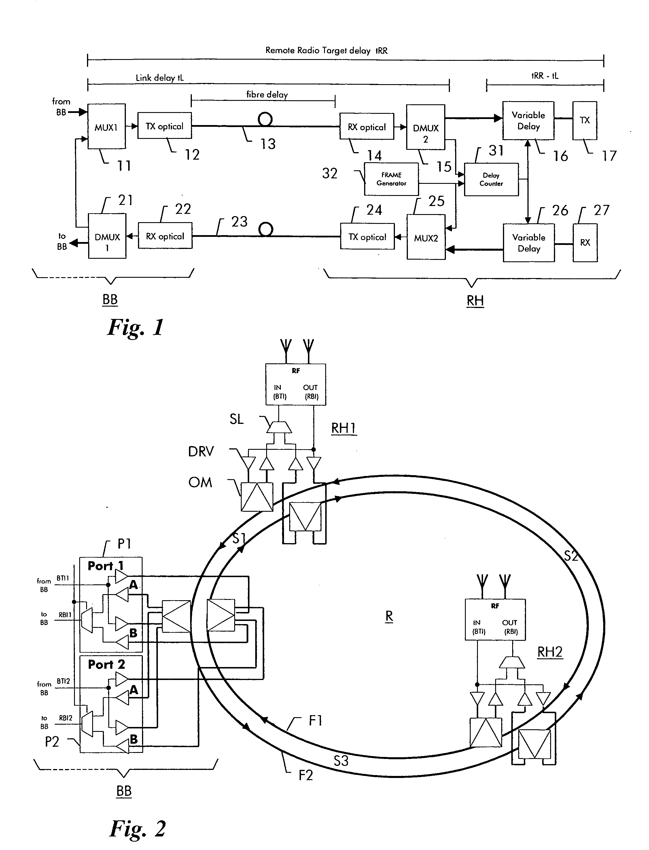
[0014] A base station with the optical interfaces of a baseband unit BB and one remote radio frequency (RF) ead RH hown by way of example in FIG. 1. The baseband unit BB as such is not shown in the figure. In transmit direction, the baseband signal from the baseband unit is fed to a multiplexer 11, which is connected to an optical transmitter 12. Transmitter 12 is connected via an optical fiber 13 to an optical receiver 14 of RF head RH. Optical receiver 14 leads to a demultiplexer 15. The signal extracted by demultiplexer 15 is connected via a variable delay circuit 16 to a radio transmitter 17. In receive direction, a radio receiver 27 in the RF head is connected via a variable delay circuit 26 to a multiplexer 25, which leads to an optical transmitter 24 of the RF head. Transmitter 24 is connected via an optical fiber 23 to an optical receiver 22 of the baseband unit. A demultiplexer extracts baseband signals received from the RF heads and forwards them to the baseband unit BB (n...


PUM


Abstract

A radio base station has a baseband unit (BB) and multiple RF heads (RH1, RH2), which are interconnected by means of a bi-directional two-fiber optical ring (R). Each RF head (RH1, RH2) has a delay counter (31) for determining a propagation delay (tL) on the ring (R) and a variable delay circuit (16, 26) for compensating a difference between the propagation delay on the ring and a predefined target delay (tRR). The delay counter counts (31) the delay between a test signal sent on the first fiber (F1) of the ring to the baseband unit and a received test signal looped back by the baseband unit on the second fiber (F2) of the ring.

Description

FIELD OF THE INVENTION [0001] The present invention relates to the field of telecommunications and more particularly to a radio base station with multiple radio frequency heads for use in a cellular radio network. [0002] The invention is based on a priority application, EP 04290047.2, which is hereby incorporated by reference. BACKGROUND OF THE INVENTION [0003] In a cellular radio network, a certain service area is covered by several radio base stations, which are connected to a mobile switching center to serve calls to and from mobile users within the service area. In the new UMTS standard, such a radio base station is also termed a “node B”. A radio base station contains a baseband unit and at least one antenna unit. In order to increase radio coverage and capacity, modern base stations use several sector antennas. [0004] In order to increase flexibility of the base stations, it is desirable to allow the antennas to be located remote from the baseband unit. This has led to the dev...

Claims


Application Information

Patent Timeline
IPC IPC(8): H04B10/2575H04B10/275H04W88/08
CPCH04B10/25756H04W88/085H04B10/2755
Inventor SULZBERGER, UWELANGE, KELD
Owner RPX CORP
Why Eureka
Try Eureka