
Fuel cell and method of operating the same

a fuel cell and fuel cell technology, applied in the field of fuel cells, can solve the problems of insufficient electrical energy taken out, inability to achieve stable power generation, and inability to supply oxygen-containing air to the power generation cells, and achieve the effect of stable power generation and simple structur

Inactive Publication Date: 2005-07-14
SONY CORP
View PDF3 Cites 0 Cited by
  • Summary
  • Abstract
  • Description
  • Claims
  • Application Information

AI Technical Summary

Benefits of technology

[0010] An advantage of the present invention is to provide a fuel cell capable of performing stable power generation in which air is supplied to or exhausted from power generation cells by an air supply / exhaust mechanism capable of removing water accumulated in gas conduits with a simple structure, and a method of operating the same.
[0011] In an embodiment of the present invention, there is provided a fuel cell including power generation cells, and an air supply / exhaust mechanism for supplying air to or exhausting air from the power generation cells, wherein the air supply / exhaust mechanism includes a press control means for substantially periodically varying the pressure of air supplied to or exhausted from the power generation cells.
[0012] The air supply / exhaust mechanism for supplying air to or exhausting air from the power generation cells in the fuel cell according to an embodiment of the present invention has a structure in which a cylinder provided with a spiral form groove portion is disposed in an air supply pipe. A gap capable of supplying a fixed quantity of air to the power generation cells is formed between the inside wall of the air supply pipe and the surface of the cylinder. When the cylinder is rotated, air in a quantity greater than the quantity of air supplied into a gas conduit at steady-state time is supplied to each power generation cell through the groove portion. Due to the increase in the quantity of air supplied into the gas conduits connecting between the air supply pipe and the power generation cells, the pressure of air in the gas conduits is increased, whereby water generated in the power generation cells can be discharged.
[0013] The pressure control means in the fuel cell according to an embodiment of the present invention resides in that the cylinder provided with the spiral form groove portion in the surface thereof is rotated, whereby the quantity of air supplied to each power generation cell can be increased according to the rotation period of the cylinder, and the pressure of air supplied to or exhausted from the power generation cells can be varied substantially periodically. The quantity of air supplied in a fixed quantity and the quantity of air supplied to each power generation cell increased according to the rotation period of the cylinder can be set to required magnitudes by varying the cross sectional area of the gap between the air supply pipe and the cylinder and the cross sectional area of the groove portion provided in the surface of the cylinder. In addition, the period of the increase in the quantity of air supplied to each power generation cell can be varied by varying the revolution number of a shaft rotation motor for rotating the cylinder. Since the rotation period of the cylinder can be varied, optimum operating conditions can be set according to the conditions in generating power by the fuel cell.
[0014] In accordance with another embodiment of the present invention, there is provided a method of operating a fuel cell including a low-pressure air supply / exhaust step for supplying or exhausting air at a predetermined pressure, and a high-pressure air supply / exhaust step for supplying or exhausting air at a pressure higher than that in the low-pressure air supply / exhaust step, whereby the fuel cell is operated while substantially periodically varying the pressure of air supplied to or exhausted from power generation cells. In the fuel cell of the stack structure in which the power generation cells are disposed in parallel relative to an air supply pipe, water generated in the power generation cells disposed in parallel relative to the air supply or exhaust pipes can be removed by providing a pressure difference between the air supply and the air exhaust through the common air supply or exhaust pipes.
[0015] According to an embodiment of the present invention, at the time of supplying air to the power generation cells connected in parallel to the air supply or exhaust pipes, the cylinder provided with the spiral form groove portion is rotated in the air supply or exhaust pipes, whereby the pressure of air supplied to the power generation cells can be regulated, and water accumulated in the gas conduits which are air supply passages for the power generation cells can be discharged efficiently.

Problems solved by technology

When a fuel cell of the above-mentioned structure is used as an energy supply system, the reaction between hydrogen and oxygen results in formation of water as a by-product on the air pole side where oxygen is supplied, and the flow of air at the time of supplying oxygen-containing air to the power generation cells may be thereby hindered.
There may be cases where, in the process of continuously performing power generation, water as the by-product stands as an obstacle to the flow of air through the gas conduits, so that stable power generation is not achieved and electrical energy is not taken out sufficiently.
However, arrangement of the valves 105 for on the basis of each power generation valve 101 can provide a complicated structure and in increase in the number of component parts.
Further, the power generation cells 101 corresponding to the closed valves 105 are not supplied with air, and, therefore, stable power generation cannot be achieved.
However, these air supply systems are complicated in structure and are therefore not suited to a fuel cell for practical use.
Besides, in the case of providing a greater quantity of electrical energy, the amount of water accumulated in the gas conduits 102 is also increased, so that it becomes difficult for air to flow smoothly in the gas conduits 102, thus making it very difficult, if not impossible, to achieve stable power generation.

Method used


Image

  • Fuel cell and method of operating the same
  • Fuel cell and method of operating the same
  • Fuel cell and method of operating the same

Examples


Embodiment Construction

[0028] The present invention generally relates to fuel cells. In an embodiment, a fuel cell includes an air supply / exhaust mechanism capable of smoothly flowing air in gas conduits into which air is supplied and performing stable power generation as described below in detail with reference made to the drawings.

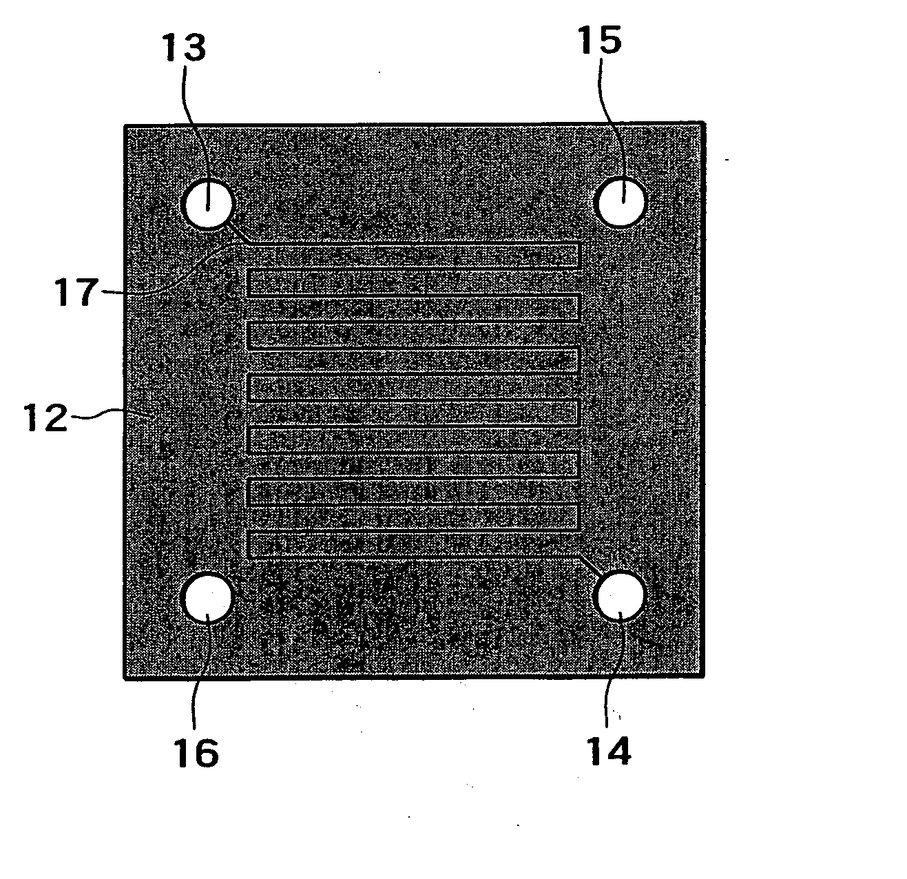
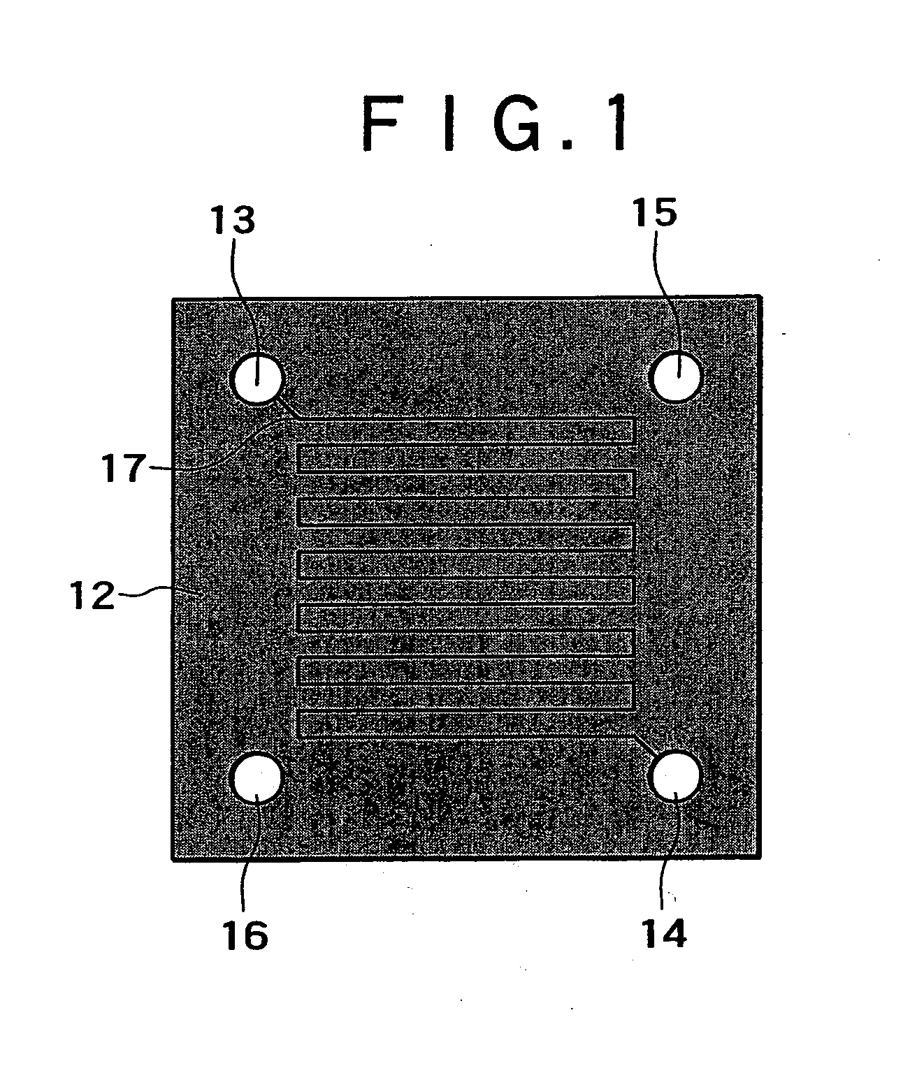
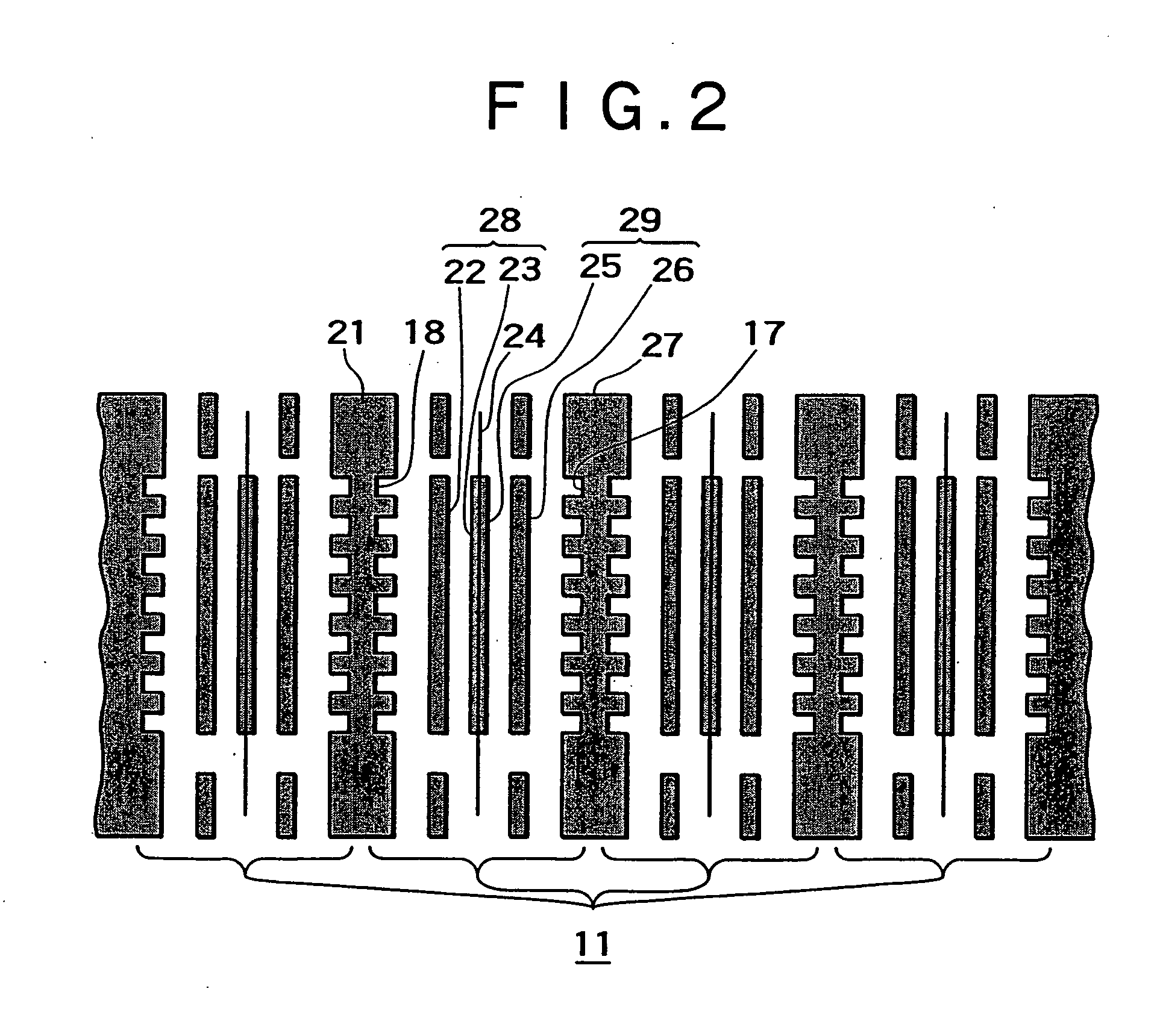
[0029]FIG. 1 shows a perspective plan view of a fuel cell according to an embodiment of the present invention. An end plate 12 is disposed at an end face of a stack of power generation cells 11 to constitute the fuel cell as shown in FIGS. 1 and 2.

[0030] The end plate 12 is a thin sheet form in shape, and the outside shape thereof is rectangular according to an embodiment of the present invention. The outside shape is not limited to the rectangular shape, and it suffices that the outside shape is substantially the same as that of the stack of the power generation cells. In this regard, the outside shape of the end plate 12 may be circular, triangular or other polygonal shape...


PUM

PropertyMeasurementUnit
depthaaaaaaaaaa
thicknessaaaaaaaaaa
widthaaaaaaaaaa

Abstract

Fuel cells and methods of operating same are provided. In an embodiment, fuel cells include cylinders each provided with a spiral form groove portion in the surface thereof and disposed in air supply or exhaust pipes are rotated, wherein the amount of air supplied to power generation cells can be sequentially increased on a cell-by-cell basis, and water formed at the power generation cells can be discharged by sequentially raising the pressure of air. In this regard, each power generation cell is constantly supplied with not less than a fixed quantity of air, thus stable power generation can be achieved.

Description

CROSS REFERENCE TO RELATED APPLICATIONS [0001] The present application is a continuation of U.S. patent application Ser. No. 10 / 219,037, filed on Aug. 14, 2002, the disclosure of which is incorporated herein by reference. The present application claims priority to Japanese Patent Application No. P2001-247400 filed on Aug. 16, 2001 herein incorporated by reference to the extent permitted by law.BACKGROUND OF THE INVENTION [0002] The present invention relates to a fuel cell of the stack type in which power generation cells are stacked, and a method of operating the same. More particularly, the invention relates to a fuel cell in a stacked arrangement which includes an air supply / exhaust mechanism capable of sequentially removing water generated at air poles on a cell-by-cell basis, and a method of operating same. [0003] Fuel cells can produce electrical energy from an electrochemical reaction between hydrogen and oxygen have been demanded to be enhanced in function and be further redu...

Claims


Application Information

Patent Timeline
Patent Type & Authority Applications(United States)
IPC IPC(8): H01M8/24H01M8/04H01M8/10
CPCH01M8/04089Y02E60/50H01M8/04104H01M8/04H01M8/24
Inventor KANAI, CHIAKI
Owner SONY CORP
Learn More