Mobile vehicle sensor array

a sensor array and mobile technology, applied in the direction of instruments, process and machine control, braking systems, etc., can solve the problems of difficult to detect objects, prior art cleaning machines have limited vision, and cleaning machines have problems detecting objects directly ahead of cleaning machines, so as to improve the detection accuracy, improve the detection of objects, and increase the confidence level

Inactive Publication Date: 2005-07-14
SJ AUTOMATION
View PDF16 Cites 35 Cited by
  • Summary
  • Abstract
  • Description
  • Claims
  • Application Information

AI Technical Summary

Benefits of technology

[0007] To further improve detection of objects, an additional feature of the present invention is that the sensor array has the at least two overlapping beam zones where the data of the object location is computed utilizing sensor fusion software. The fusion software increases a confidence level for detecting the object ahead of the mobile vehicle because as the mobile vehicle travels toward the object, the object is detected in successive multiple overlapping beam zones. Another feature of the present invention is that the first and the second sensors are selected from a group consisting of piezoelectric sensors, electrostatic sensors, magnetorestrictive sensors, infrared sensors and light detecting and ranging (LIDAR) sensors.
[0008] Another feature in an alternative preferred embodiment of the present invention is providing impedance tapering for the sensors of the array to increase the accuracy of the detection of objects. Specifically, the sensor array further includes the first sensor recess-mounted within a first acoustically tapered matching network and the second sensor recess-mounted within a second acoustically tapered matching network. In one preferred embodiment of the present invention, the first acoustically tapered impedance matching network comprises a first conically tapered horn and the second acoustically tapered impedance matching network comprises a second conically tapered horn. More specifically in one alternative preferred embodiment of the present invention, the first acoustically tapered impedance matching network comprises a first conically tapered horn, wherein the first conically tapered horn transitions a small piston diameter acoustical beamwidth radiating from the first sensor to a larger piston diameter acoustical beamwidth. More specifically in one alternative preferred embodiment of the present invention, the second acoustically tapered impedance matching network comprises a second conically tapered horn, wherein the second conically tapered horn transitions a small piston diameter acoustical beamwidth radiating from the second sensor to a larger piston diameter acoustical beamwidth.
[0009] In one preferred embodiment, a plurality of sensors are asymmetrically spaced-apart sensors that are mounted on the mobile vehicle and that are asymmetrically spaced-apart sensors are not located in the same plane. In another preferred embodiment, a plurality of sensors are symmetrically spaced-apart sensors that are mounted on the mobile vehicle and that all symmetrically spaced-apart sensors are located in the same plane. In this preferred embodiment of the present invention, an engineer may custom position the plurality of sensors to maximize forward area coverage depending on the shape of the mobile vehicle. In one alternative preferred embodiment of the present invention, the spaced-apart sensors comprise sonar sensors each emitting a beamwidth within the range of approximately 12 degrees to approximately 15 degrees. In another preferred embodiment of the present invention, the spaced-apart sensors comprise light emitting and ranging detectors (LIDAR) sensors.
[0010] It is another feature of the present invention that the spaced-apart sensors may be arranged in multiple configurations to maximize a field of vision of the mobile vehicle. In particular, in one preferred embodiment of the present invention, the spaced-apart sensors are configured or reconfigured in a U-shape arrangement to achieve an approximate 195-degree field of view for a mobile vehicle comprising a rectangular shape with rounded corners. It is another feature of the present invention, the spaced-apart sensors for the mobile vehicle that are configurable and reconfigurable by a user to suit the shape of the mobile vehicle so that different data coverage areas may be programmed into the sensor array to maximize detection of the objects.

Problems solved by technology

Prior art robotic cleaning machines have problems detecting objects directly ahead of the cleaning machine because sensors mounted on the cleaning machine emit beams that don't accurately detect the presence of an object directly ahead of the left forward and the right forward edges of the cleaning machine.
Further, prior art cleaning machines have a limited field of vision because the sensors don't accurately detect an object's location ahead of a cleaning machine.
Other problems with prior art cleaning machines include that the mobile vehicle transmits beams that interfere with the received beams so that is it difficult to detect objects close to the cleaning machines, and these mobile vehicles have limited built-in redundancy for detecting objects directly in the path of the cleaning machines.

Method used


Image

  • Mobile vehicle sensor array
  • Mobile vehicle sensor array
  • Mobile vehicle sensor array

Examples


Embodiment Construction

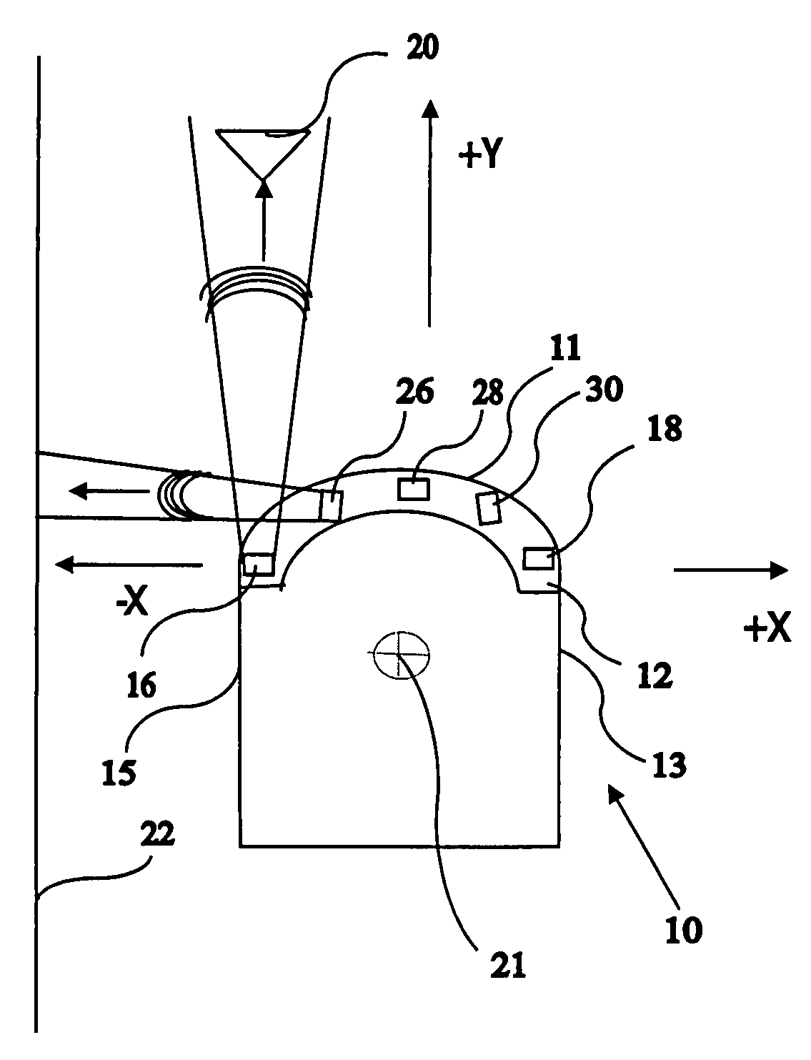
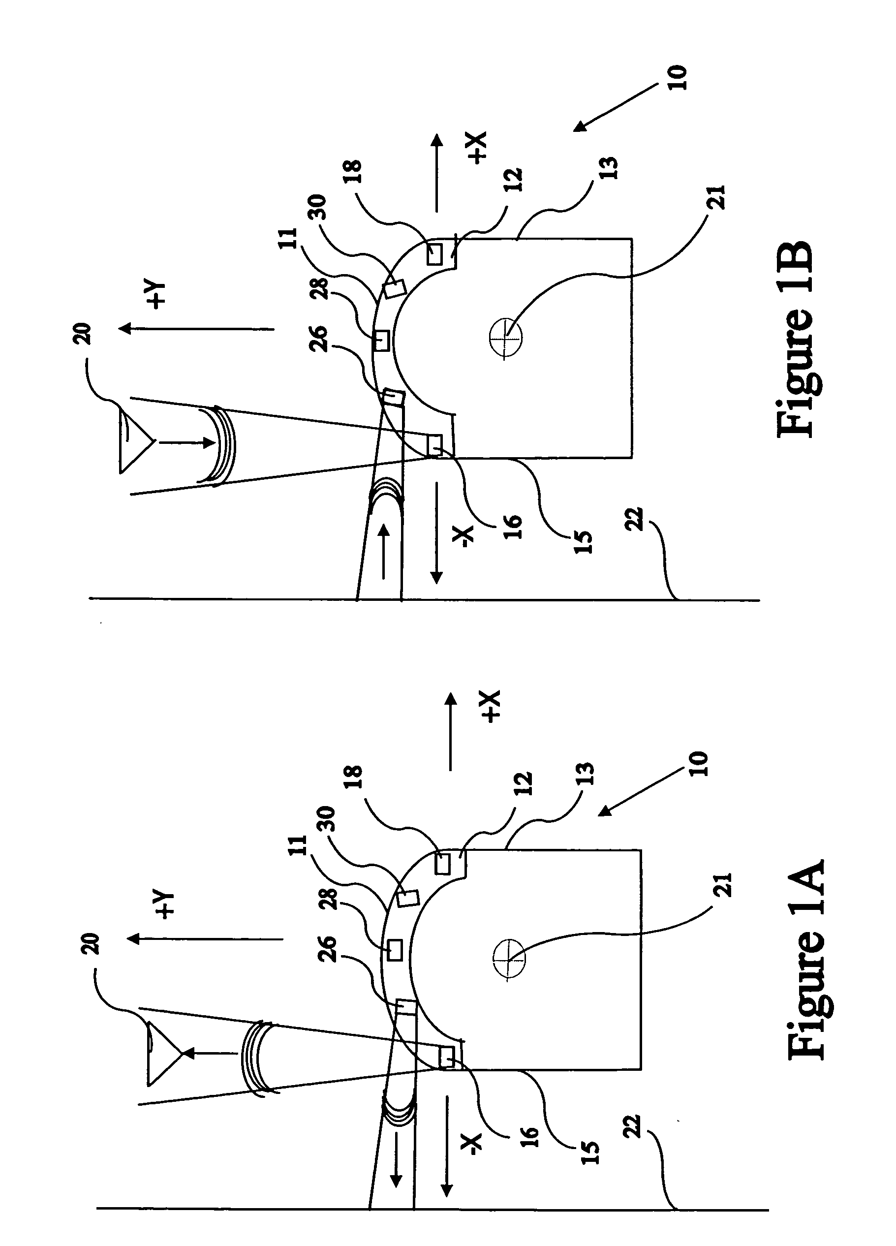
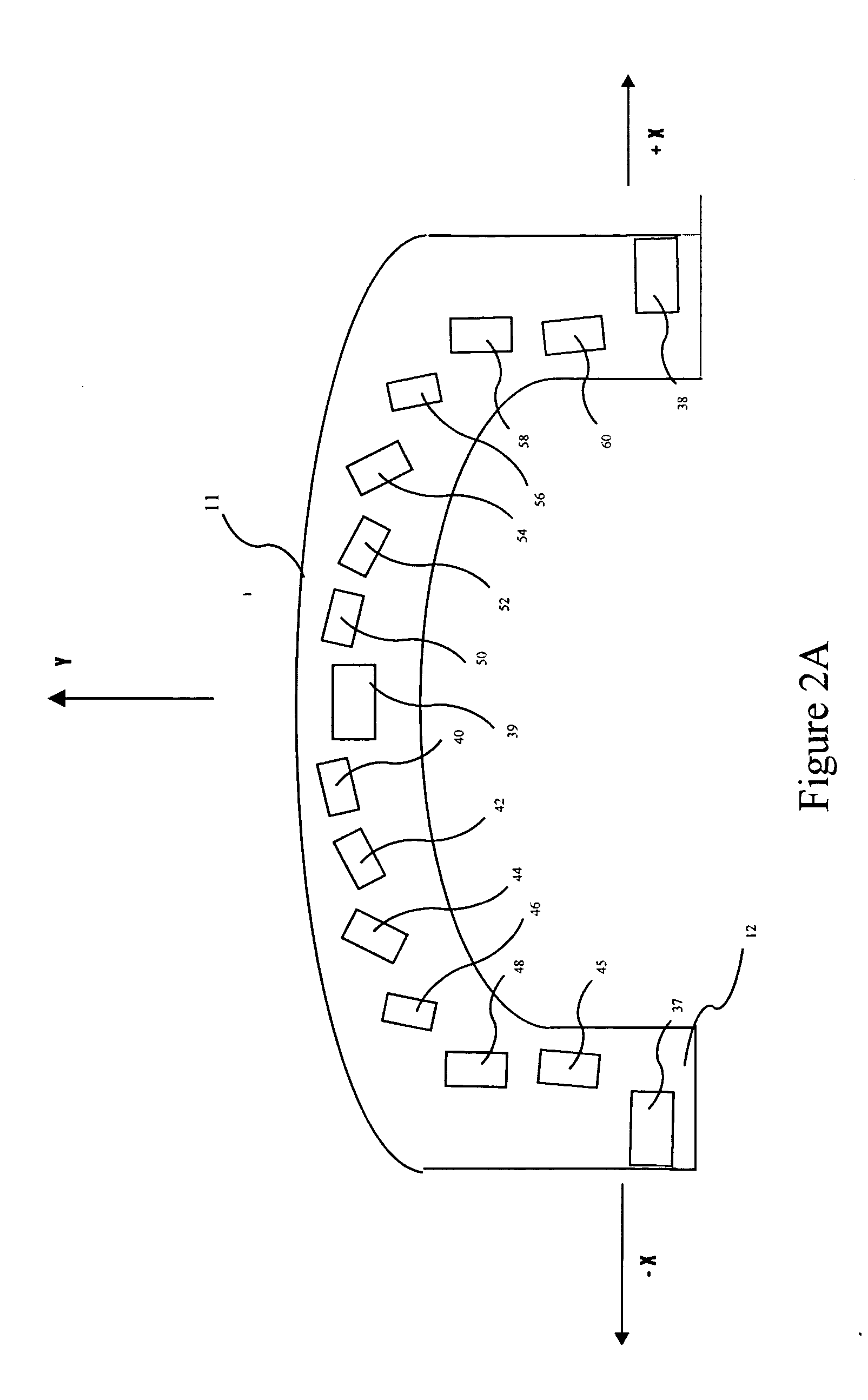
[0023] The present invention provides an improved sensor array for a mobile vehicle. Accordingly, the primary objective is to provide an improved sensor array so that the mobile vehicle detects more accurately the location of objects ahead of the mobile vehicle. In particular, the primary objective of the present invention is to provide a mobile vehicle traveling in a forward direction having a front, a first side, a second side and a vertical axis of rotation with improved detection ability of objects ahead of the mobile vehicle.

[0024]FIG. 1 is a sensor array mounted on a mobile vehicle. A mobile vehicle 10 comprises a sensor array 12. In one preferred embodiment of the present invention, mobile vehicle 10 is a unmanned cleaning machine for floors. In the alternative, the mobile vehicle may be any automatic or semiautomatic machine that will follow a programmed path with a minimum or no human supervision. In this preferred embodiment, mobile vehicle 10 is traveling in the forward ...


PUM


Abstract

An improved sensor array for a mobile vehicle. More particularly, the primary objective of the present invention is to provide mobile vehicle (10) traveling in a forward direction with a sensor array (12). Sensor array (12) comprises a first sensor (16) mounted to mobile vehicle (10) at a maximum lateral distance from said vertical axis of rotation (21) near a first side of mobile vehicle (10) and a second sensor (18) mounted to mobile vehicle (10) at a maximum lateral distance from said vertical axis of rotation (21) near a second side of mobile vehicle (10). First sensor (16) and the second sensor (18) emit object detecting beams for detecting an object (39) ahead of mobile vehicle (10). A plurality of other object detecting beams are emitted obliquely to the object detecting beams of sensor (16) and sensor (18). These other beams, in conjunction with the object detecting beams from sensor (16) and sensor (18) form zones of overlapping beam coverage for better detection of objects.

Description

REFERENCE DOCUMENT [0001] This application is related to the subject matter discussed in Disclosure Document No. 536507 submitted on Aug. 8, 2003, to the Commissioner for Patents entitled “Reconfigurable 195 Degree Sonar Vision with Peripheral Vision.”TECHNICAL FIELD [0002] This invention relates to a sensor array for a mobile vehicle. More particularly, this invention relates to a sensor array for a mobile vehicle traveling in a forward direction having a first sensor and a second sensor. The first sensor is disposed on the mobile vehicle at a maximum lateral distance from said vertical axis of rotation near a first side. The second sensor is disposed on the mobile vehicle at a maximum lateral distance from said vertical axis of rotation near a second side. The first sensor emits a first object detecting beam ahead of the mobile object. The second sensor emits a second object detecting beam ahead of the mobile object. The first object detecting beam overlaps with other obliquely em...

Claims


Application Information

Patent Timeline
Patent Type & Authority Applications(United States)
IPC IPC(8): G05D1/02G06F7/00
CPCG05D1/0242G05D1/024
Inventor JACOBS, STEVEN
Owner SJ AUTOMATION
Why Eureka
Try Eureka