Route designing method

a routing and routing technology, applied in the field of routing design, can solve the problems of waste of bandwidth, waste of bandwidth, waste of bandwidth, etc., and achieve the effect of efficiently accommodating user traffic and performing the route design

Inactive Publication Date: 2005-07-14
FUJITSU LTD
View PDF34 Cites 129 Cited by
  • Summary
  • Abstract
  • Description
  • Claims
  • Application Information

AI Technical Summary

Benefits of technology

[0050] According to the invention, it is possible to provide the technology capable of easily performing the route design for efficiently accommodating the user traffic.

Problems solved by technology

Therefore, in the case of performing the communications between the two sites each subscribing different bandwidth, traffic equal to or larger than the access link subscription bandwidth on the receiving side is sent from a transmitting side, and it might happen that an excessive quantity of traffic is to be discarded just anterior to the access link on the receiving side.
As viewed from the relay network, this means that the futile traffic to be discarded has been forwarded, which is a waste of bandwidth.
The waste of bandwidth might cause a decline of a quality of service to other users.
However, there is multiplicity of accommodation sites, and a traffic request from the site is assumed such that a maximum speed of the traffic from the site is given simply as subscription bandwidth of the access link and it is not determined which site receives the traffic request and how many traffic requests are given thereto.
There is not any method of effectively determining the utilizable bandwidth.

Method used


Image

  • Route designing method
  • Route designing method
  • Route designing method

Examples


embodiment 1

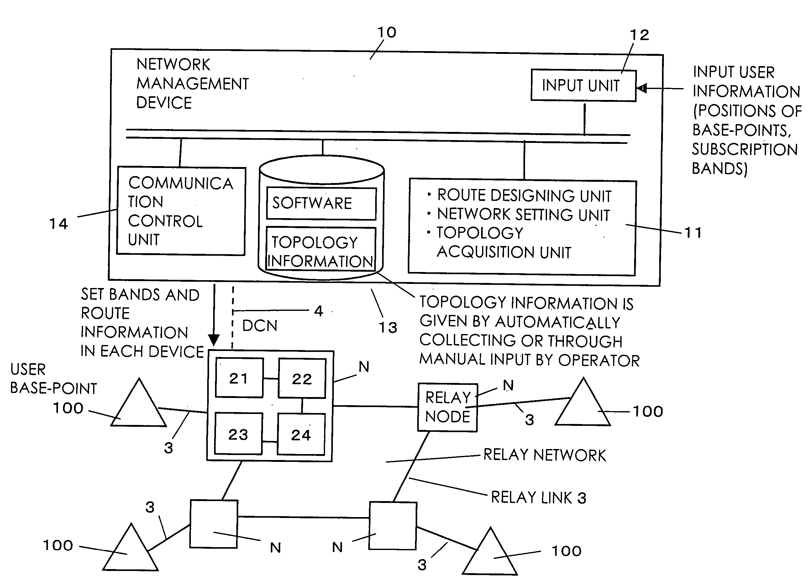
[0092]FIG. 1 is a view showing a whole architecture of a network system by way of an embodiment 1 of the invention.

[0093] As shown in FIG. 1, the network system in the embodiment 1 includes a network management device 10 having a route designing function, relay nodes (network devices) N for relaying a user traffic, and a network that connects these devices to each other. The respective relay nodes N are connected via links 3, thus configuring a relay network. A network 4 for setting may be, for example, Ethernet. The setting network 4 may connect the network management device 10 to each of all the relay nodes and may also connect the network management device 10 to only a single unspecified relay node N, wherein this relay node N may send a setting command (setting information) to other relay nodes N via a relay network for transferring (forwarding) the user traffic.

[0094] The relay node N includes an input unit 21 for accepting an input of the traffic of communications (the user ...

embodiment 2

[0123] As compared with the embodiment 1 discussed above, an embodiment 2 has a different method of allocating the communication bands by the route designing unit, and other configurations are the same. Therefore, the repetitive explanations of the same configurations as those in the embodiment 1 discussed above, are omitted.

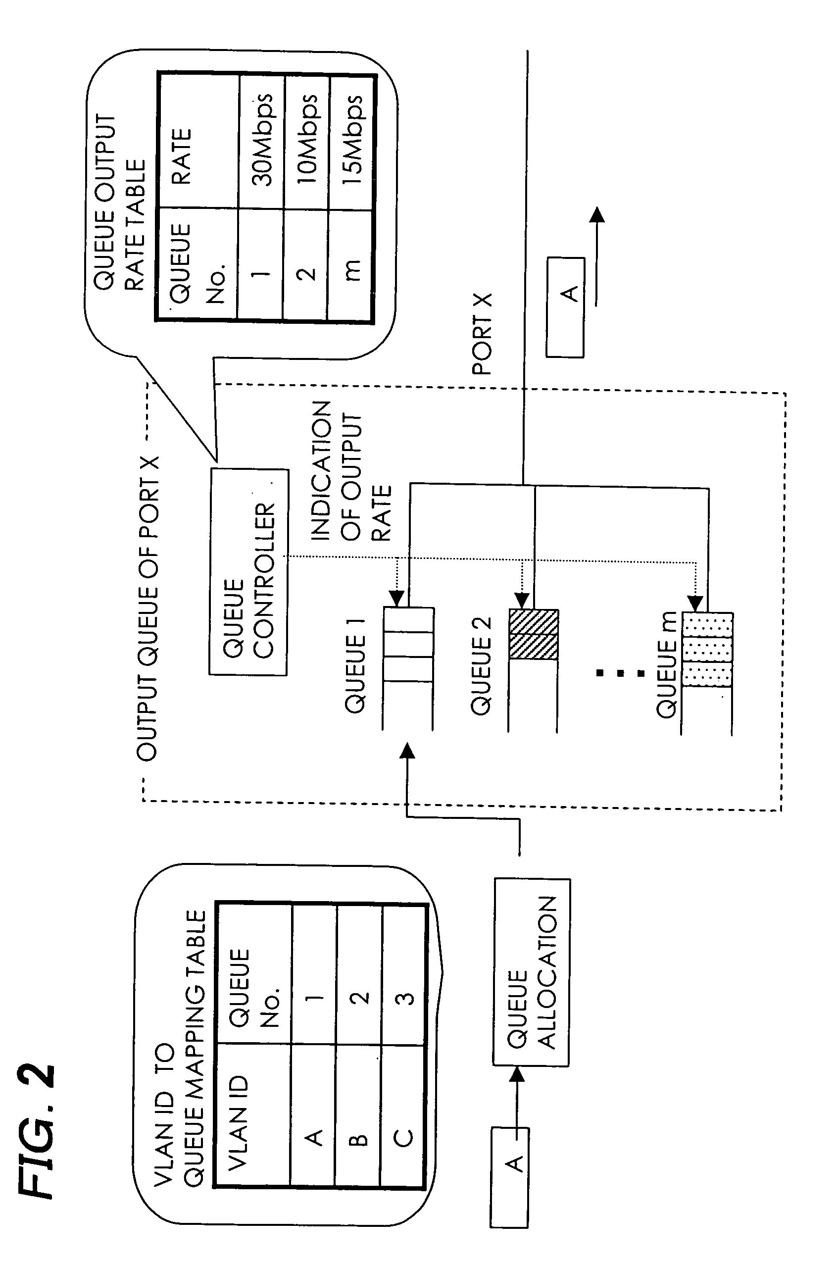
[0124] The route designing unit in the embodiment 2 obtains the route that connects all the user sites in the same way as the above-mentioned, and allocates the communication bands so that an upper limit of the communication bandwidth allocated to an arbitrary port is equal to or lower than a sum of upper limits of the communication bands allocated to other ports. Namely, the smaller of total values of the traffics relayed by the relay nodes N at both ends of each link on the route, is adopted as an allocation band.

[0125] The allocation bands herein indicate output rates allocated to the output ports at both ends thereof. The link allocation bands are determin...

embodiment 3

[0148] As compared with the embodiment 2 discussed above, an embodiment 3 has a different method of determining the communication route by the route designing unit, and other configurations are the same. Therefore, the repetitive explanations of the same configurations as those in the embodiment 2 discussed above, are omitted.

[0149] In the case of using the bandwidth allocating method according to the embodiment 2 discussed above, the route having the minimum consumable bandwidth invariably exists on a shortest route tree in which any one of the nodes within the relay network serves as an origin (root).

[0150] Such being the case, it is possible to determine the route having the minimum consumable bandwidth at a low cost of calculation (algorithm) in the case of effecting the bandwidth allocations.

[0151] Namely, the routing setting unit of the network management device 10 obtains the shortest route trees with the respective relay nodes each serving as the root, then acquires the r...


PUM


Abstract

To provide a technology of easily conducting a route design for efficiently accommodating user traffic. On the occasion of designing a communication route between user sites in a network management device connecting to a relay node in a network that connects a plurality of user sites to each other through a plurality of relay nodes and links, there is accepted an input of user information containing information about bandwidth of an access link serving as a link for connecting each of the user sites to the relay node, and information showing the relay node connecting to the user site via the access link, topology information of the network for relaying the communications between the user sites is acquired, a communication relay port and a communication non-relay port are obtained based on the user information and the topology information, an upper limit of the communication bandwidth available for the user on the communication relay port is obtained, a route design so that the user sites are connected by a tree-shaped route is performed, and a result of the route design is outputted.

Description

BACKGROUND OF THE INVENTION [0001] The invention relates to a technology enabling a network to be utilized at a high efficiency by properly designing a route along which nodes relay traffic and also a traffic allocation in the network configured by connecting a plurality of nodes. [0002] The invention is a technology employed for managing and operating, for instance, a virtual LAN service (Example: wide area Ethernet (registered trademark)) for providing multipoint-to-multipoint communications among user sites extending over a plurality of points. To be specific, the invention relates to a technology of determining a route for accommodating user traffic and bandwidth on a user-by-user basis to attain highly-efficiency accommodation while ensuring a sufficient speed to such an extent as not to exceed a subscribed bandwidth of a connection line (access link) between the user site and a relay network in a virtual LAN operation system. [0003] As a service for providing the multipoint-to...

Claims


Application Information

Patent Timeline
Patent Type & Authority Applications(United States)
IPC IPC(8): G06F15/173H04L12/28H04L12/46H04L45/122
CPCH04L12/4641H04L12/4675H04L41/0896H04L41/145H04L45/00H04L45/54H04L45/12H04L45/122H04L45/30H04L45/48H04L45/02
Inventor NAGATA, AKIRAUENO, HITOSHIMIYAZAKI, KEIJI
Owner FUJITSU LTD
Why Eureka
Try Eureka