Switched noise filter circuit for a dc-dc converter

a noise filter circuit and converter technology, applied in the direction of dc-dc conversion, power conversion systems, instruments, etc., can solve the problems of insufficient reduction ripple, unsatisfactory frequency synchronization, premature switching, etc., and achieve the effect of reducing the effect of extraneous electromagnetic noise coupled into vfb

Active Publication Date: 2005-07-21
SEMICON COMPONENTS IND LLC
View PDF8 Cites 82 Cited by
  • Summary
  • Abstract
  • Description
  • Claims
  • Application Information

AI Technical Summary

Benefits of technology

[0012] The switching control circuit also includes a switched noise filter circuit arranged to apply an offset voltage to Vfb during at least one of the “on” and “off” time intervals, with the offset voltage disconnected from the feedback voltage by the beginning of the immediate modulated time interval or shortly thereafter, so that Vfb is allowed to gradually decay toward V2. When the offset voltage is properly applied, the effect of extraneous electromagnetic noise coupled into Vfb is reduced.

Problems solved by technology

Noise in the feedback voltage can lead to jitter, undesirable frequency synchronizations, premature switching, or other malfunctions.
This solution suffers from several deficiencies.
The reduced ripple might be insufficient to ensure jitter-free switching, especially if the unfiltered value of the ripple was already small.
Secondly, the RC filter introduces a phase shift into the feedback voltage.
This phase shift might reduce the stability margin of the converter, and the converter might become unstable as a result.

Method used


Image

  • Switched noise filter circuit for a dc-dc converter
  • Switched noise filter circuit for a dc-dc converter
  • Switched noise filter circuit for a dc-dc converter

Examples


Embodiment Construction

[0036] The present switched noise filter circuit reduces the adverse effect of electromagnetic noise on DC-DC converters which employ the instantaneous output voltage to regulate the output voltage. As such, it is useful with many different DC-DC converter configurations, including those employing constant-on-time valley-voltage control, constant-off-time peak-voltage control, constant-frequency peak-voltage or valley-voltage control, hysteretic control, or Vsquare control.

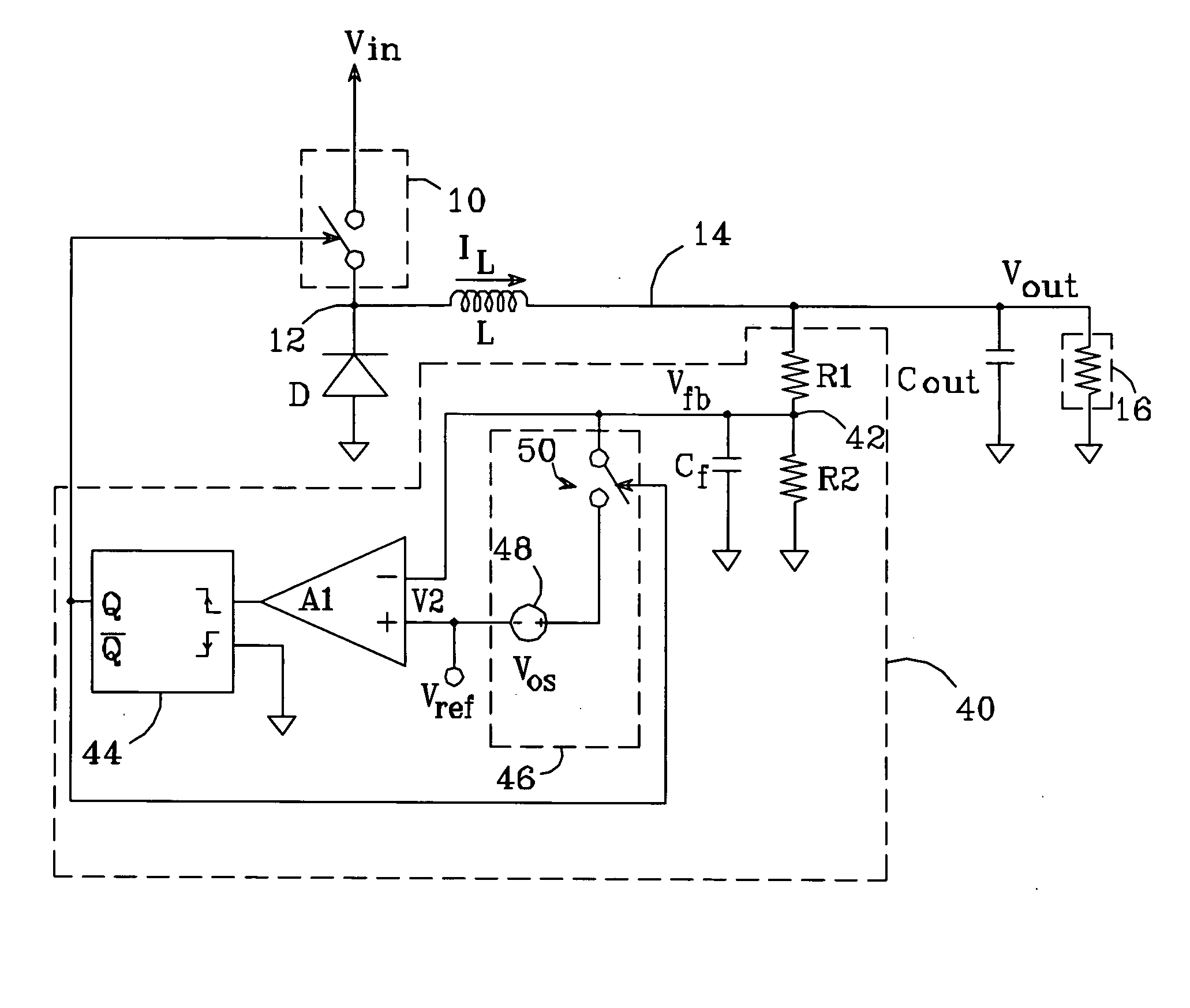
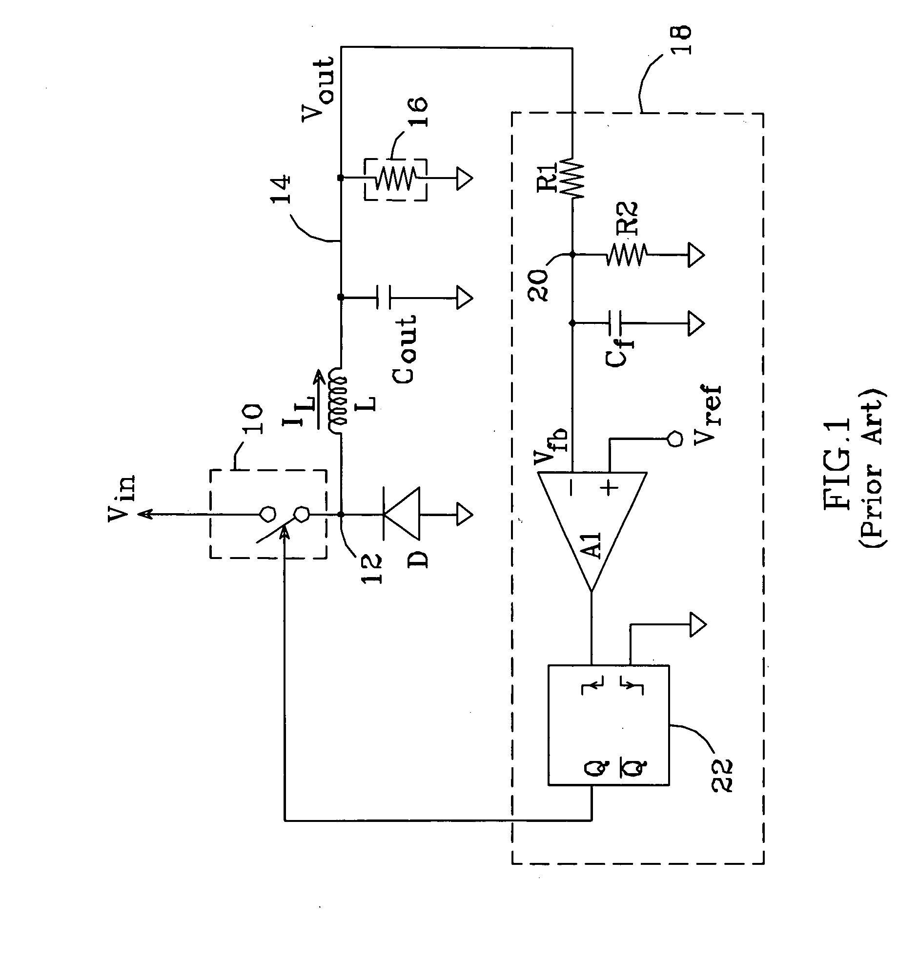
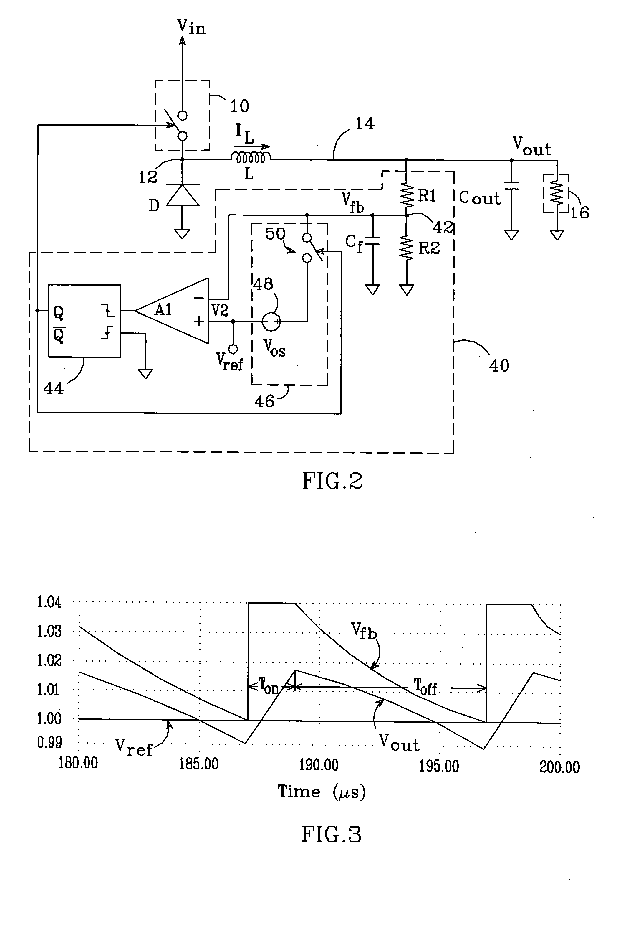
[0037] An embodiment of the present invention as it might be used with a DC-DC converter which uses constant-on-time valley-voltage control is shown in FIG. 2. As in FIG. 1, a switching element 10 is connected between input voltage Vin and node 12, and inductor L is connected between node 12 and output terminal 14 at which regulated output voltage Vout is provided. Inductor current IL feeds a load network comprising capacitance Cout and load 16. The switching of element 10 is controlled by a switching control cir...


PUM


Abstract

A switched noise filter circuit for DC-DC converters which use the instantaneous output voltage to establish the converter's duty ratio. The converter cycles the switching element on and off for time intervals Ton and Toff, respectively. A switching control circuit includes a filter capacitance connected between the feedback node and ground, and a comparator which compares a feedback voltage Vfb with a fixed voltage Vref; at least one of Ton and Toff is a “modulated” interval which is terminated when Vfb crosses Vref due to the discharge of the filter capacitance. A switched noise filter circuit applies an offset voltage to Vfb during at least one of Ton and Toff, with the offset voltage disconnected from Vfb by the beginning of the modulated interval or shortly thereafter. When the offset voltage is properly applied, the effect of extraneous electromagnetic noise coupled into Vfb is reduced.

Description

BACKGROUND OF THE INVENTION [0001] 1. Field of the Invention [0002] This invention relates to the field of DC-DC converters, and particularly to methods of mitigating the adverse effects of electromagnetic noise sources on such converters. [0003] 2. Description of the Related Art [0004] An important class of DC-DC converter uses the instantaneous output voltage to establish the duty ratio required for maintaining a regulated output. This class includes: 1) converters which do not employ a voltage-error amplifier, e.g., the various valley-voltage and peak-voltage regulators, and the hysteretic regulator; and 2) converters that employ the “Vsquare” technique (described, for example, in U.S. Pat. No. 5,770,940). [0005] An example of such a converter is shown in FIG. 1. A switching element 10 is connected between an input voltage Vin and a node 12, and an inductor L is connected between node 12 and an output terminal 14 at which a regulated output voltage Vout is provided. Switching ele...

Claims


Application Information

Patent Timeline
Patent Type & Authority Applications(United States)
IPC IPC(8): H02M3/156
CPCH02M3/156H02M1/44
Inventor REDL, RICHARDLI, YUXINREIZIK, GABOR
Owner SEMICON COMPONENTS IND LLC
Why Eureka
Try Eureka