Magnetoresistive smart switch

a smart switch and magnetoresistive technology, applied in the field of high-reliable switches, can solve the problems of difficult to locate, switch failure, and potentially dangerous and/or economically costly conditions

Inactive Publication Date: 2005-07-21
HONEYWELL INT INC
View PDF13 Cites 8 Cited by
  • Summary
  • Abstract
  • Description
  • Claims
  • Application Information

AI Technical Summary

Problems solved by technology

Many of these applications involve complex systems, such as those used on aircraft or oil wells, which rely on a large number of switches.
Many of these switches experience intensive use in these systems and, as a result, fail because their parts simply wear out.
Switches can also fail because the...

Method used


Image

  • Magnetoresistive smart switch
  • Magnetoresistive smart switch
  • Magnetoresistive smart switch

Examples


Embodiment Construction

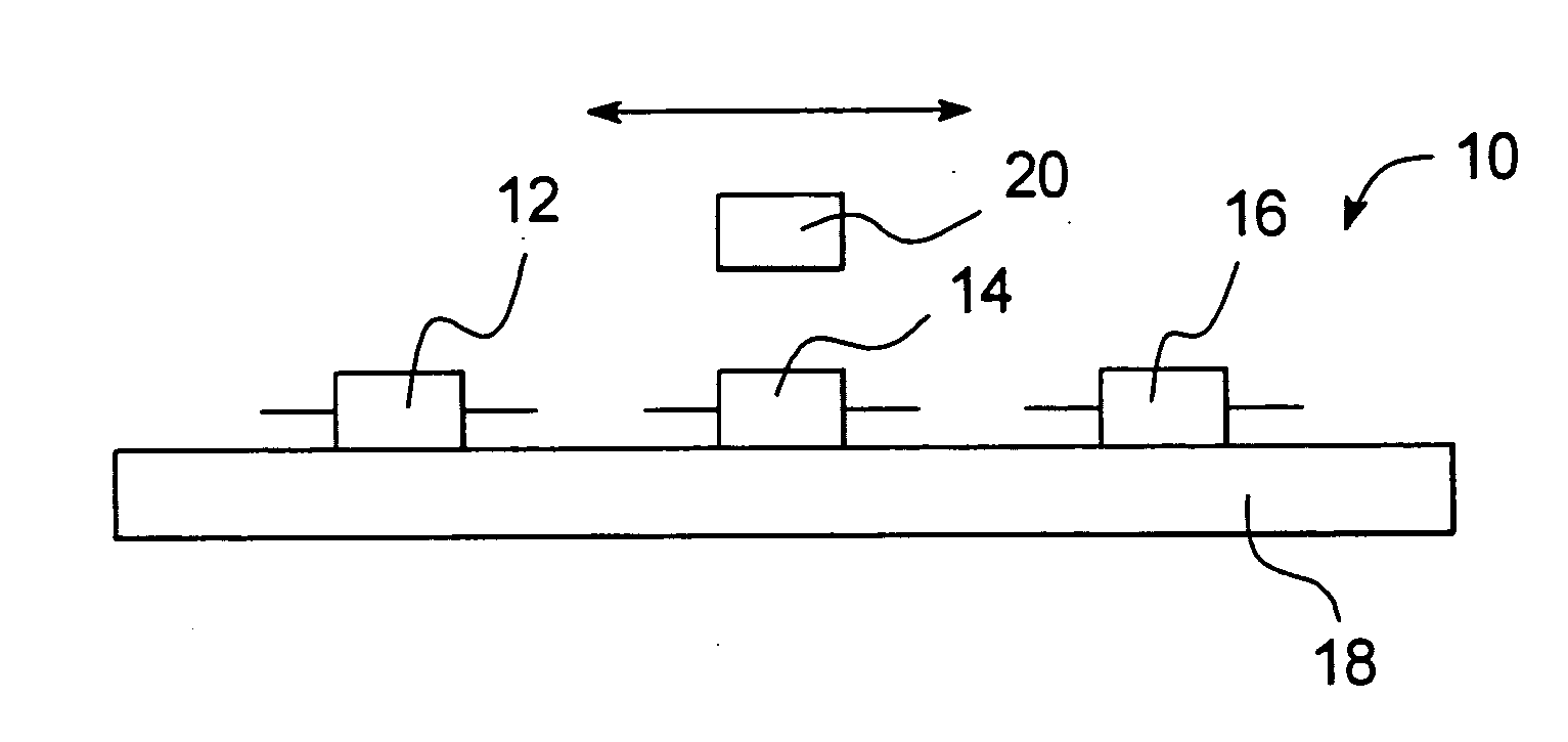
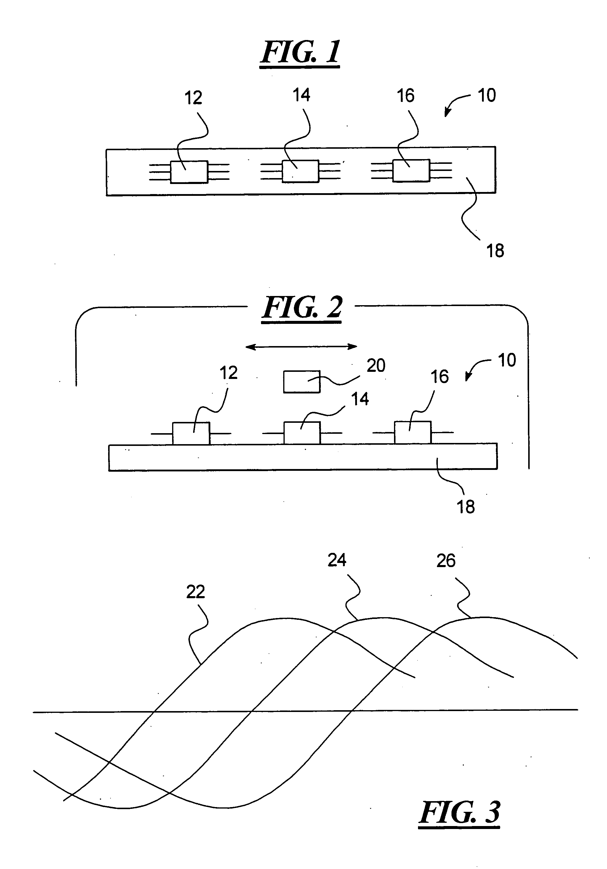
[0018] As shown in FIGS. 1 and 2, a switch 10 according to one embodiment of the present invention includes three magnetoresistive sensors 12, 14, and 16 mounted on a mounting surface 18. The magnetoresistive sensor 14 is located between the magnetoresistive sensors 12 and 16, and the magnetoresistive sensors 12 and 16 are positioned on either side of the magnetoresistive sensor 14. The magnetoresistive sensors 12, 14, and 16 sense the position of a switch operator 20, such as an actuator, a door, an oscillating shaft, etc., as the switch operator 20 moves over the magnetoresistive sensors 12, 14, and 16 in the direction shown by the double ended arrow of FIG. 2.

[0019] As the switch operator 20 passes over it, each of the magnetoresistive sensors 12, 14, and 16 is mounted on the mounting surface 18 so as to produce a corresponding one of the voltage outputs 22, 24, and 26 shown in FIG. 3. Accordingly, the magnetoresistive sensor 12 produces the voltage output 22, the magnetoresisti...


PUM


Abstract

A smart switch has a magnetic operator, at least one magnetic sensor located to sense movement of the magnetic operator, and a processor that processes an output of the magnetic sensor so as to detect right and left over travel ranges and a normal operating range of the magnetic operator. The magnetic sensor may be a magnetoresistive sensor.

Description

TECHNICAL FIELD OF THE INVENTION [0001] The present invention relates to a highly reliable switch that has no contact with a moving object and that is capable of detecting its own failure and / or over travel range. BACKGROUND OF THE INVENTION [0002] Switches are used in a variety of applications to control the on and off states of loads, to sense the proximity or position of input devices, to provide inputs to data processing systems, and so on. Many of these applications involve complex systems, such as those used on aircraft or oil wells, which rely on a large number of switches. Many of these switches experience intensive use in these systems and, as a result, fail because their parts simply wear out. Switches can also fail because they are driven or otherwise travel out of range. [0003] Many of the switches used in complex systems provide critical functions. When a switch that provides a critical function fails, the failure can result in a potentially dangerous and / or economicall...

Claims


Application Information

Patent Timeline
IPC IPC(8): G01B7/14G01B7/30G01D3/08G01D5/14G01R33/02G01R33/06H01F7/02H01H55/00H01H67/00H03K17/97
CPCG01D5/14G01D3/08
Inventor WAN, HONGMALLISON, EDGAR R.FREEMAN, MICHAEL L.
Owner HONEYWELL INT INC
Why Eureka
Try Eureka