Transmission power control device and method thereof, computer program for transmission power control device, and radio transmitter

a transmission power and control device technology, applied in the direction of transmission, gain control, amplifiers with semiconductor devices/discharge tubes, etc., can solve the problems of inviting a degradation not being able to meet the needs of radio frequency characteristics, etc., to achieve the effect of minimizing loss

Inactive Publication Date: 2005-07-21
LENOVO INNOVATIONS LTD HONG KONG
View PDF6 Cites 15 Cited by
  • Summary
  • Abstract
  • Description
  • Claims
  • Application Information

AI Technical Summary

Benefits of technology

[0019] The present invention has been made in view of the conventional problems described above. The object of the present invention is to provide a transmission power control device which ca

Problems solved by technology

Namely, in the conventional radio transmitter shown in FIG. 10, there is a drawback of inviting a degradation of RF (Radio Frequency) characteristic due to the fact that the coupler 110 is inserted in

Method used


Image

  • Transmission power control device and method thereof, computer program for transmission power control device, and radio transmitter
  • Transmission power control device and method thereof, computer program for transmission power control device, and radio transmitter
  • Transmission power control device and method thereof, computer program for transmission power control device, and radio transmitter

Examples


first modification

(First Modification)

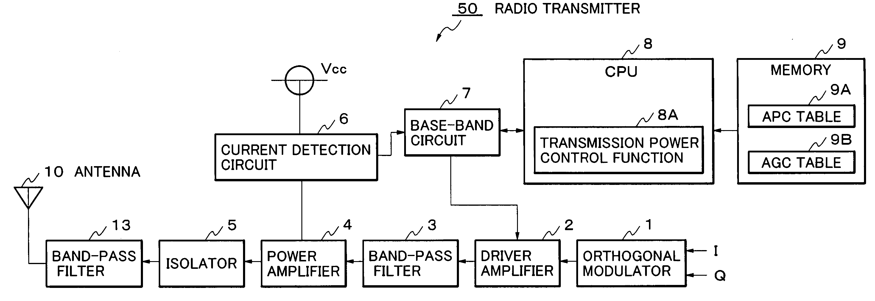
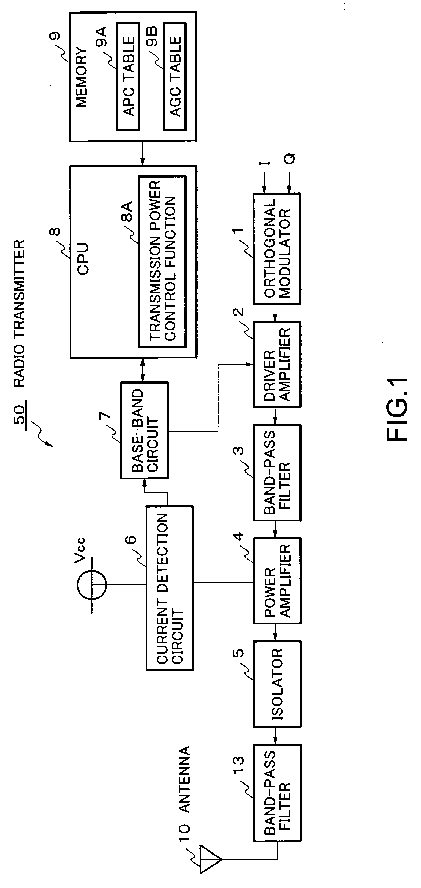
[0069]FIG. 9 is a block diagram showing a circuit configuration of a radio transmitter in a first modification according to this embodiment. The circuit configuration of a radio transmitter 50A according to this embodiment further provides a temperature sensor 11 and an A (analog) / D (digital) conversion circuit 12 in addition to providing the same configuration as the above-described radio transmitter 50 (FIG. 1). The temperature sensor 11 detects temperatures of the device itself and the environment thereof.

[0070] The A / D conversion circuit 12 converts a detection signal detected by the temperature sensor 11 to a digital data. The CPU 8, when a transmission power control function 8B according to this modification is performed, acquires the detection result by the temperature sensor 11 through the A / D conversion circuit 12.

[0071] In addition, in the circuit configuration shown in FIG. 9, the duplicating description is omitted by giving the same reference numera...

second modification

(Second Modification)

[0084] In this modification, to the APC table 9A for the power amplifier 4 and the AGC table 9B for the driver amplifier 2, a linear interpolation is carried out. By carrying out such linear interpolation, fine transmission power control can be realized even in nonlinear portions.

[0085] More specifically, the linear interpolation of the APC table 9A and the AGC table 9B means that in regions where the 1.0 changes occur linearly the interval of sampling values to be described in the table are decimated while in nonlinear regions sampling values to be described in the table are set finely.

[0086] Here, one example of the linear interpolation of the APC table 9A in this modification will be described. In the characteristic 31 exemplified in FIG. 3, the region from 5.0 dBm to 20.0 dBm is apparently nonlinear. However, even in this region, looking at a short section (for example, 1 to 4 dBm interval), it can be regarded as linear. So, in this modification, when desc...


PUM


Abstract

A transmission power control device which amplifies in a driver amplifier 2, and in a power amplifier 4 to which the output from the driver amplifier is inputted, so that the power of a signal to be transmitted may become predetermined target transmission power, detects an electric-current which flows to the power amplifier 4 from a power supply, and adjusts the gain of the driver amplifier 2 based on this detected electric-current.

Description

BACKGROUND OF THE INVENTION [0001] 1. Field of the Invention [0002] The present invention relates to the field of a control technology of transmission power in a radio-communications apparatus (a radio transmitter), such as a mobile terminal device. [0003] 2. Description of the Related Art [0004] In a radio-communications apparatus, such as a mobile terminal device, transmission power required for transmitting a radio signal varies depending on factors, such as the dispersion and the temperature characteristics of built-in components which constitute a radio-communications circuit a radio transmitter) For this reason, in such radio-communications circuit, an APC (Automatic Power Control) circuit is generally employed. [0005]FIG. 10 is a block diagram showing a circuit configuration of a conventional radio transmitter having the APC function. [0006] In FIG. 10, I and Q signals denote the orthogonal signals to be transmitted. An orthogonal modulator 101 carries out an orthogonal modul...

Claims


Application Information

Patent Timeline
IPC IPC(8): H03G3/20H03G3/30H04B1/04
CPCH03F2200/504H04B1/04H03G3/3042
Inventor ANDO, YOSHIAKI
Owner LENOVO INNOVATIONS LTD HONG KONG
Why Eureka
Try Eureka