Radio-frequency identification (RFID) tag employing unique reception window and method therefor

a radio frequency identification and unique technology, applied in the field of low-power radiofrequency identification tags and systems, can solve the problems of inability to determine the sniffer circuit and the limited system of the above-mentioned system, and achieve the effect of low-power operation

Inactive Publication Date: 2005-07-21
AEROSCOUT
View PDF7 Cites 79 Cited by
  • Summary
  • Abstract
  • Description
  • Claims
  • Application Information

AI Technical Summary

Problems solved by technology

However, it is not possible for a sniffer circuit to determine whether or not the tag is being addressed by the WLAN system, as the sniffer does not include circuitry decode messages in order to determine a recipient.
Therefore, the above-mentioned system is limited in that tag configuration and operational characteristics are fixed and cannot be adjusted by the system.

Method used


Image

  • Radio-frequency identification (RFID) tag employing unique reception window and method therefor
  • Radio-frequency identification (RFID) tag employing unique reception window and method therefor
  • Radio-frequency identification (RFID) tag employing unique reception window and method therefor

Examples


Embodiment Construction

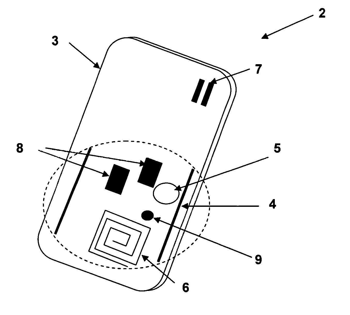
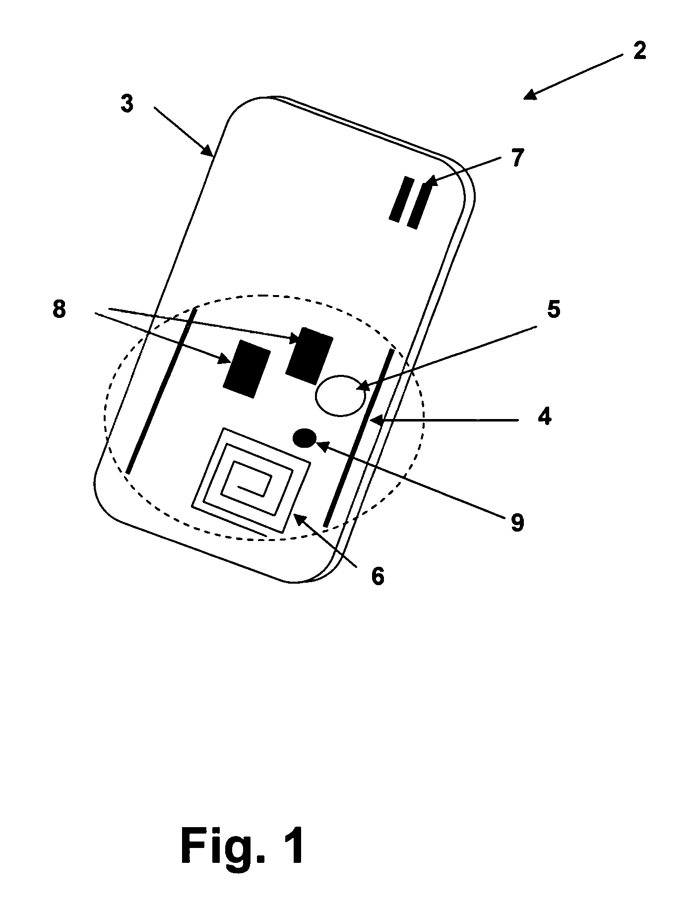
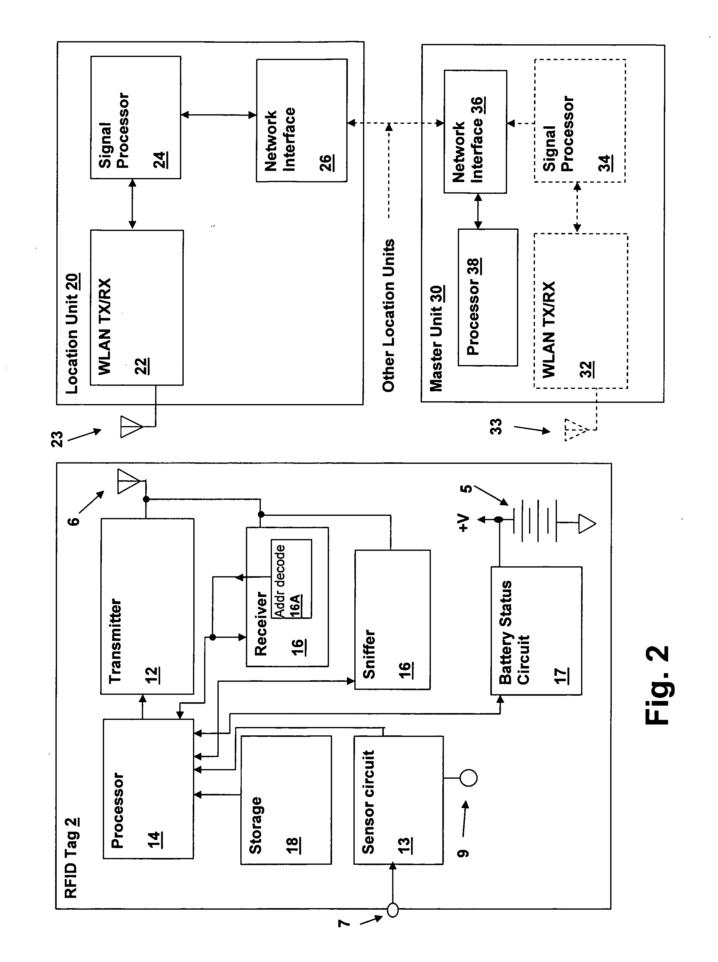
[0018] The present invention includes improvements to the radio-frequency identification (RFID) tag disclosed in the above-incorporated parent application, which includes illustrative embodiment of RFID tags for use in a wireless local area network (WLAN) environment. The RFID tags of the present invention include circuitry implementing a reception window during which receiver circuits are powered subsequent to a periodic transmit interval of the RFID tags. The WLAN or other system may address individual tags thereby without requiring that the tag receiver be constantly active and thereby receive all signals transmitted by the system. It should be understood by those of ordinary skill in the art that the present invention applies to other forms of identification tags, as well. For example, low frequency identification tags may be made and operated in accordance with embodiments of the present invention that are not WLAN-compatible.

[0019] Referring to the figures, and in particular ...


PUM


Abstract

A radio-frequency identification (RFID) tag employing a unique reception window and method for operating the tag system provides low-power operation for enhanced tag battery life, while providing addressable tags that can receive commands and data from the system, which can be a wireless local area network (WLAN) incorporating location finding for locating the tags. Interference with other tags and other transmitters is prevented by either using a sniffer circuit to determine that no network transmission is in progress, or by using a special non-interfering coding sequence. A receiver within the tag is operated for a predetermined period of time after a periodic transmission is made from the tag, and an address decoder determines if the tag is being addressed. The receiver can receive data and / or commands after being addressed and is shutdown if the window time elapses, the tag is not addressed, or at the completion of data / command transfer.

Description

CROSS-REFERENCE TO RELATED APPLICATIONS [0001] The present application is a Continuation-in-Part of U.S. patent application Ser. No. 10 / 274,698 filed on Oct. 18, 2002 and is further related to previously-filed United States Patent Applications assigned to the same assignee: “METHOD AND APPARATUS FOR ENHANCING SECURITY IN A WIRELESS NETWORK USING DISTANCE MEASUREMENT TECHNIQUES”, Ser. No. 10 / 156,244, filed May 24, 2002; “METHOD AND APPARATUS FOR INTRUSION MANAGEMENT IN A WIRELESS NETWORK USING PHYSICAL LOCATION DETERMINATION”, Ser. No. 10 / 171,427, filed Jun. 13, 2002; and “METHOD AND SYSTEM FOR LOCATION FINDING IN A WIRELESS LOCAL AREA NETWORK”, Ser. No. 10 / 225,267 filed Aug. 20, 2002. The specifications of the above-referenced U.S. Patent Applications are herein incorporated by reference.BACKGROUND OF THE INVENTION [0002] 1. Field of the Invention [0003] The present invention relates generally to wireless networks, and more specifically, to a low power radio-frequency identification...

Claims


Application Information

Patent Timeline
Patent Type & Authority Applications(United States)
IPC IPC(8): G01S5/06G01S13/76G01S13/87
CPCG01S5/06G01S13/765G01S13/878G06K19/07345G06K19/0717G06K19/0723G06K19/0705
Inventor ALJADEFF, DANIELAMSALEM, REUVEN
Owner AEROSCOUT
Why Eureka
Try Eureka