Motion detection using a shock sensor in a remote tire pressure monitoring system

a technology of motion detection and remote tire pressure monitoring, which is applied in vehicle tyre testing, instruments, roads, etc., can solve the problems of ineffective previous techniques, inability to detect motion,

Active Publication Date: 2005-07-21
SENSATA TECHNOLOGIES INC
View PDF47 Cites 99 Cited by
  • Summary
  • Abstract
  • Description
  • Claims
  • Application Information

AI Technical Summary

Benefits of technology

[0014] By way of introduction, a tire monitor for mounting to a vehicle as part of a remote tire monitoring system includes a tire condition sensor to produce a tire condition signal, a controller coupled to the tire condition sensor to control operation of the tire monitor, and a radio circuit coupled to the controller to transmit radio signals based at least in part on the tire condition signal. A piezoelectric or piezoceramic sensor is coupled to the controller of the tire monitor to produce a motion signal indicating motion of the tire monitor.

Problems solved by technology

One problem with such systems has been the need to program the location of the transmitters at the central station.
These previous techniques have been limited in effectiveness.
The magnetic programming technique may be subject to interference and crosstalk, for example in a factory where many such tire monitors are being assembled with tires and vehicles.
The apparatus for transmitting a long wave activation signal and generating a long wave identification signal therefrom is too expensive for some applications.
The two-way data communication technique requires demodulation of the received radio signals at the wheel well and coaxial cabling back to the central controller, both of which add to the cost of the system.
The tangential acceleration which must be sensed requires a highly sensitive accelerometer which may be prohibitively expensive in the current application.
A further limitation of some of these prior techniques is the manual operation requiring activation by a service technician.
The roll switch included in prior tire monitors is necessarily subject to a lot of forces during use, including high-g forces during vehicle motion and shock and vibration as the tire traverses rough pavement.
Also, the roll switch tends to degrade in performance over time and become a non-ideal switch.
Still further, presently available roll switches are not true surface-mount devices of the type that can automatically be assembled on a printed circuit board, and the presently available roll switch is relatively expensive.

Method used


Image

  • Motion detection using a shock sensor in a remote tire pressure monitoring system
  • Motion detection using a shock sensor in a remote tire pressure monitoring system
  • Motion detection using a shock sensor in a remote tire pressure monitoring system

Examples


Embodiment Construction

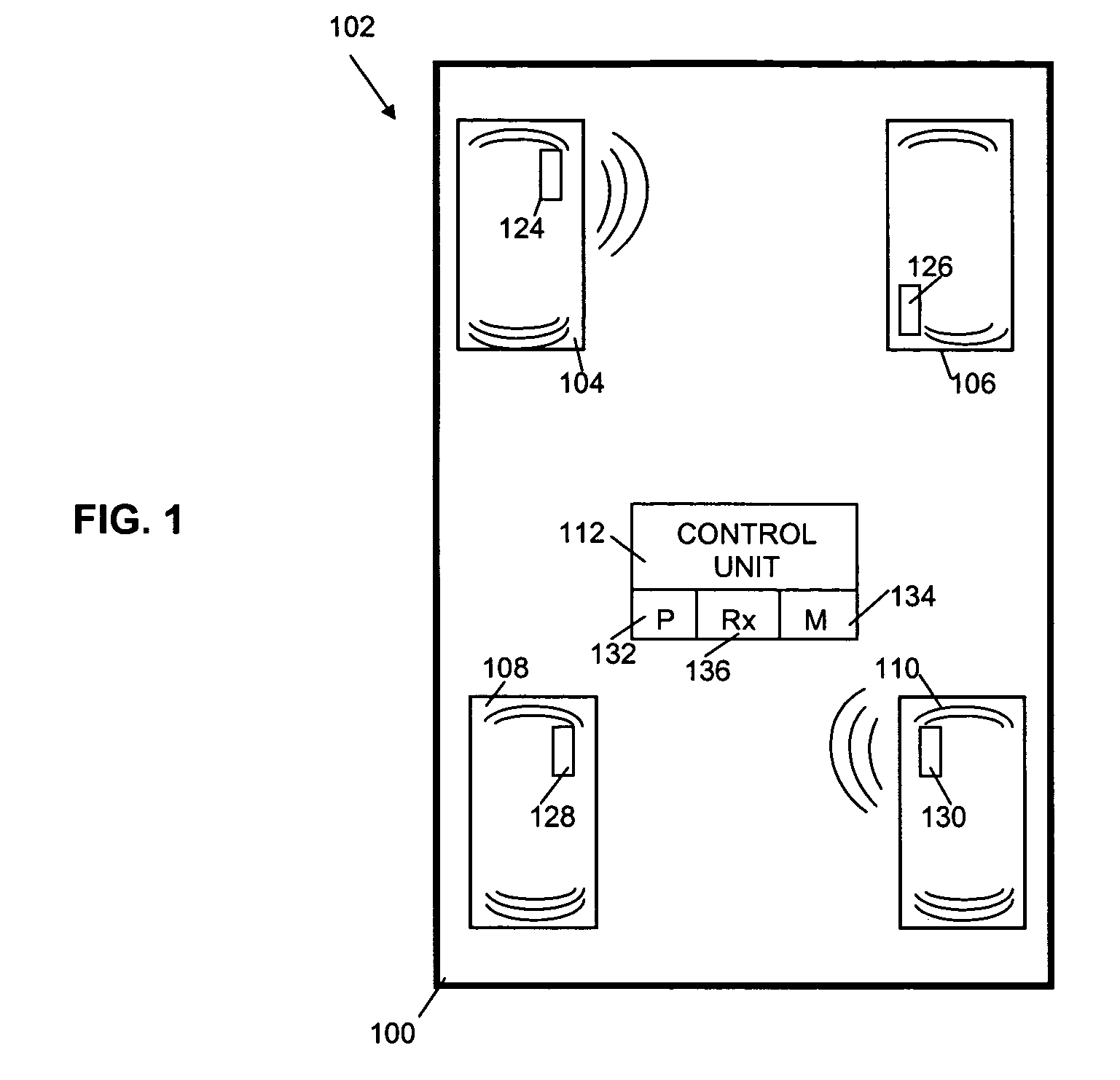
[0033] Referring now to the drawing, FIG. 1 is a block diagram of a remote tire monitor system 100 shown in conjunction with portions of a vehicle 100 with a remote tire monitor system 102. The vehicle 100 includes wheels 104, 106, 108, 110. Each wheel includes a tire mounted on a rim. In other embodiments, the vehicle 100 may have other numbers of wheels. For example, in one particular embodiment, a truck has 18 wheels.

[0034] The remote tire monitor system 102 in the illustrated embodiment includes a control unit 112 and tire monitors 124, 126, 128, 130. The tire monitors 124, 126, 128, 130 measure tire characteristics and transmit tire data for reception and processing by the control unit 112. The system 102 may include other components as well. Thus, the illustrated embodiment of FIG. 1 is exemplary only.

[0035] The remote tire monitor system 102 as illustrated in FIG. 1 includes a tire monitor associated with each wheel of the vehicle 100. Thus, a tire monitor 124 is associated...


PUM


Abstract

A tire monitor for mounting to a vehicle as part of a remote tire monitoring system includes a tire condition sensor to produce a tire condition signal, a controller coupled to the tire condition sensor to control operation of the tire monitor, and a radio circuit coupled to the controller to transmit radio signals based at least in part on the tire condition signal. A shock sensor is coupled to the controller of the tire monitor to produce a motion signal indicating motion of the tire monitor.

Description

CROSS REFERENCE TO RELATED APPLICATIONS [0001] The present application is related to U.S. application Ser. No. ______, docket number 1981 / 688, entitled “Determination of Wheel Sensor Position Using Shock Sensors and a Wireless Solution,” commonly assigned with the present application, filed on even date herewith and incorporated herein in its entirety by this reference.COPYRIGHT NOTICE [0002] A portion of the disclosure of this patent document contains material which is subject to copyright protection. The copyright owner has no objection to the facsimile reproduction by anyone of the patent document or the patent disclosure, as it appears in the Patent and Trademark Office patent file or records, but otherwise reserves all copyright rights whatsoever. BACKGROUND [0003] In one aspect, the present invention relates generally to a remote tire monitoring system and components for such a system. In other aspects, the present invention relates to methods and apparatus for automatically w...

Claims


Application Information

Patent Timeline
Patent Type & Authority Applications(United States)
IPC IPC(8): B60C23/00B60C23/04
CPCB60C23/0408
Inventor MCCALL, ALAN KENNETHSTEWART, WILLIAM DAVID
Owner SENSATA TECHNOLOGIES INC
Why Eureka
Try Eureka