Liquid ejection head

a technology of liquid ejection and ejection head, which is applied in the direction of piezoelectric/electrostrictive/magnetostrictive devices, printing, electrical apparatus, etc., can solve the problems of increasing the internal stress of the diaphragm and piezoelectric film, and the inability to achieve sufficient displacement when a driving voltage is applied

Active Publication Date: 2005-07-21
SEIKO EPSON CORP
View PDF9 Cites 11 Cited by
  • Summary
  • Abstract
  • Description
  • Claims
  • Application Information

AI Technical Summary

Benefits of technology

[0005] In order to solve the aforementioned problems, the present invention is a liquid jetting head comprising a substrate formed with a pressure chamber, a diaphragm formed on the substrate, and a piezoelectric thin fil...

Problems solved by technology

It has been conjectured that one of the causes of this bending is that the effect of internal stress occurring in the diaphragm and piezoelectric film increases relative to...

Method used


Image

  • Liquid ejection head
  • Liquid ejection head
  • Liquid ejection head

Examples


example 1

6. EXAMPLE 1

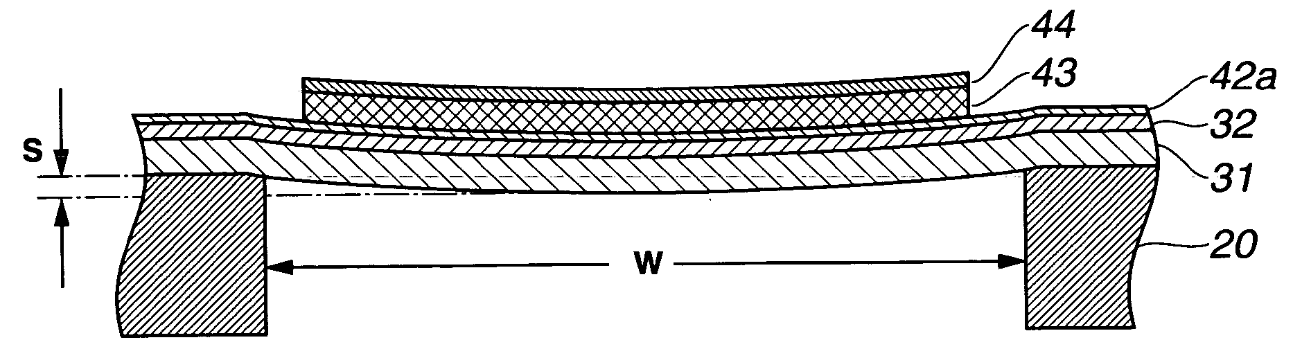
[0077] The inkjet recording head of the embodiment described above was manufactured with varying degrees of (100) face orientation of the PZT which serves as the piezoelectric thin film. By adjusting the thickness of the Ti core formed on the bottom electrode, inkjet recording heads with 8%, 33%, and 79% degrees of PZT (100) face orientation respectively were obtained. In each head, the cavity width W was set at 65 μm.

[0078] For each of these inkjet recording heads, measurements of the bending S of the diaphragm directly after manufacture (initial bending), and the bending S of the diaphragm when the applied voltage was set at zero following the application of one hundred million pulses of a 20V trapezoidal wave (post-driving bending) were taken.

[0079] In the head having an 8% (100) face orientation, the initial bending S was 230 nm, and the post-driving bending S was 280 nm. In the head having a 33% (100) face orientation, the initial bending S was 130 nm, and the pos...

example 2

7. EXAMPLE 2

[0081] A measurement of the bending S in the inkjet recording head of the embodiment described above using multi-component PZT as the piezoelectric thin film was taken. More specifically, an inkjet recording head with the piezoelectric thin film 43 constituted by lead zirconate lead titanate lead nickel niobate lead zirconate niobate, which is expressed as 0.47 PbZrO3−0.43 PbTiO3−0.05Pb (Ni1 / 3Nb2 / 3)O3−0.05 Pb (Zr1 / 3Nb2 / 3)O3, was used. As in Example 1, the cavity width W was set at 65 μm. The initial bending S was 176 nm, and the post-driving bending S was 187 nm, and hence in both cases, the bending S was no more than 0.4% of the cavity width W.


PUM


Abstract

A liquid jetting head using a piezoelectric element that is capable of obtaining sufficient displacement through the application of a driving voltage is provided. In the liquid jetting head, which comprises a substrate formed with a pressure chamber, a diaphragm formed on the substrate, and a piezoelectric thin film element formed on the diaphragm, the diaphragm bends in convex form toward the pressure chamber side, and the amount by which the diaphragm bends is no more than 0.4% of the width of the pressure chamber.

Description

TECHNICAL FIELD [0001] The present invention relates to a liquid jetting head, and more particularly to a liquid jetting head formed with a piezoelectric element and a pressure chamber whose volume is increased and decreased thereby. BACKGROUND ART [0002] A liquid jetting head uses a driving element such as a piezoelectric element to discharge ink or another liquid from a pressure chamber. The piezoelectric element comprises a piezoelectric film interposed between top and bottom electrodes. By applying a driving voltage to the electrodes, warping is produced such that the volume of the pressure chamber alters, and thus the liquid inside the cavity can be discharged. As liquid jetting heads become smaller, demands are being made for reductions in the film thickness of the piezoelectric film and the size of other parts. [0003] In a liquid jetting head having a piezoelectric film that has been reduced in thickness, however, the diaphragm and piezoelectric film sometimes remain bent eve...

Claims


Application Information

Patent Timeline
IPC IPC(8): B41J2/055B41J2/045B41J2/14H01L41/08H01L41/09H01L41/187
CPCB41J2/14233B41J2/161B41J2/1628B41J2202/03B41J2/1645B41J2/1646B41J2/1631
Inventor MURAI, MASAMI
Owner SEIKO EPSON CORP
Why Eureka
Try Eureka