
Machine Tool

a technology of hammer mechanism and machine tool, which is applied in the direction of portable percussive tools, boring/drilling equipment, drilling machines and methods, etc., can solve the problems of local deformation failure of the hammer mechanism

Active Publication Date: 2012-11-29
HILTI AG
View PDF1 Cites 5 Cited by
  • Summary
  • Abstract
  • Description
  • Claims
  • Application Information

AI Technical Summary

Benefits of technology

[0004]The volume of the pneumatic chamber sets high requirements to the tolerances of the production. Any contacting of the exciter and the beater leads the hammer mechanism to fail. During the compression of the air spring the distance of the exciter from the beater reduces to approximately 1 mm, in order to generate the pressure of 20 bar necessary for the required beating performance. The high pressure leads to a local deformation of the hammer mechanism, for example the sealing ring surrounding the beater shifting and deforming. By the mechanical and thermal constant stress of the elastic sealing ring it tends to age, making it less resistant to shifting. Even a minor shifting may then lead to a sufficient displacement of the volume of the air spring with a subsequent punctual contacting of the exciter and the beater.

Problems solved by technology

Any contacting of the exciter and the beater leads the hammer mechanism to fail.
The high pressure leads to a local deformation of the hammer mechanism, for example the sealing ring surrounding the beater shifting and deforming.

Method used


Image

  • Machine Tool
  • Machine Tool
  • Machine Tool

Examples


Embodiment Construction

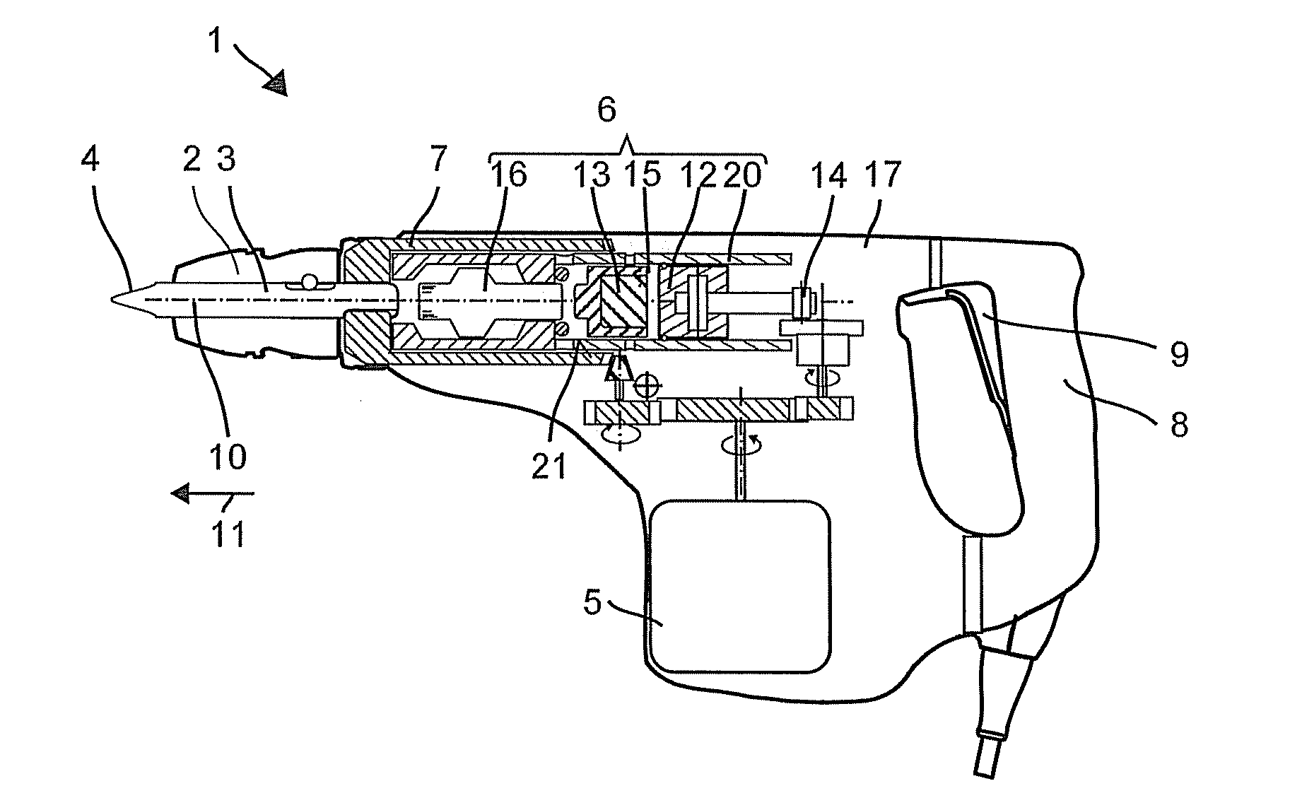
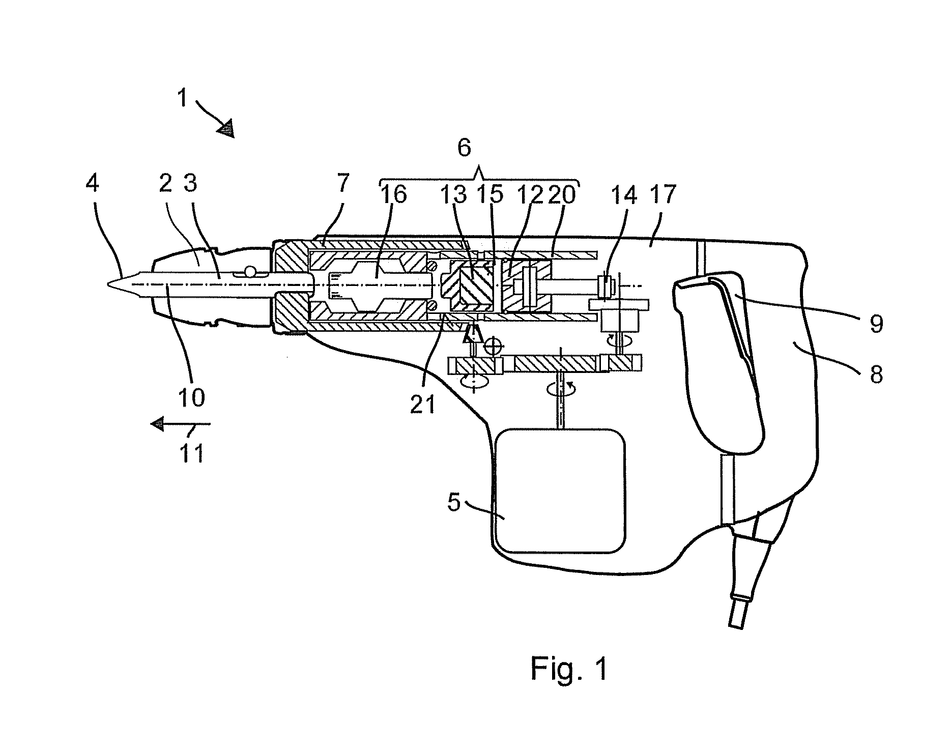
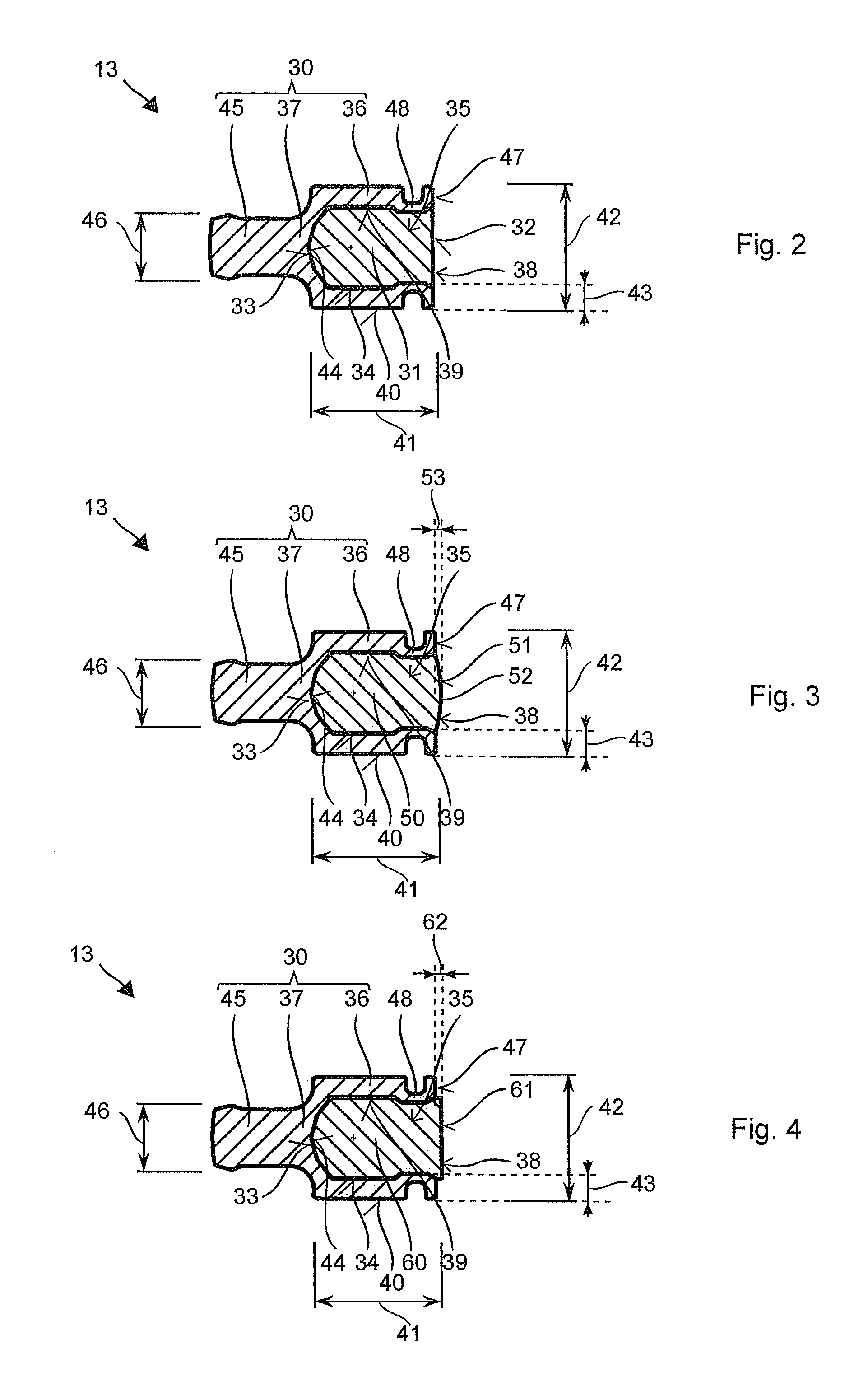
[0012]The machine tool according to one or more embodiments of the invention with a pneumatic hammer mechanism has a motorized exciter, a guiding tube, and a piston-shaped beater. The piston-shaped beater is guided by an interior surface of the guiding tube along an operating axis and with the exciter encases an air spring in the guiding tube. The beater shows a cup-shaped basic body, with an open hollow space facing the exciter, and an insert filling said hollow space. The basic body comprises a first material with a first density and the insert comprises a material with a second density, which is lower than the first density.

[0013]The lower density of the insert allows the weight of the beater to be reduced with the facial area remaining unchanged. The cup-shaped design of the preferably stiff basic body ensures that the insert is prevented from deformation by the effects of the air spring during compression. Furthermore, the insert is only subjected to minor mechanical stress, be...


PUM

PropertyMeasurementUnit
pressureaaaaaaaaaa
distanceaaaaaaaaaa
densityaaaaaaaaaa

Abstract

The machine tool according to the with a pneumatic hammer mechanism comprises a motorized exciter, a guiding tube, and a piston-shaped beater. The piston-shaped beater is guided by an interior surface of the guiding tube along an operating axis and with the exciter encloses an air spring in a guiding tube. The beater shows a cup-shaped basic body with an open hollow space facing the exciter and an inset filling the hollow space. The basic body is made from a first material with a first density and the insert is made from a material with a second density, which is lower than the first density.

Description

CROSS-REFERENCE TO RELATED APPLICATIONS[0001]The present application claims priority to German Patent Application DE 10 2011 075 765.1, filed May 12, 2011, and entitled “Handwerkzeugmaschine” (“Machine Tool”), which is hereby incorporated by reference in its entirety.BACKGROUND OF THE INVENTION[0002]The present invention relates to a machine tool with a pneumatic hammer mechanism particularly a rotary cutting chisel or a purely chiseling machine tool.[0003]In a motor-driven pneumatic hammer mechanism a piston-shaped exciter accelerates indirectly, via an air spring, a piston-shaped beater. Seals and other lateral conditions of the hammer mechanism limit the pressure of the air spring to approximately 20 bar, thus the acceleration of the beater depends on its weight and its facial area. A hammer mechanism with a rapidly operating beater requires a light beater with a large facial area. US 2009 133893 A describes a beater showing a radially extending bore in order to reduce its weight...

Claims


Application Information

Patent Timeline
Patent Type & Authority Applications(United States)
IPC IPC(8): B25D11/06
CPCB25D17/06B25D2211/068B25D2222/42B25D2222/57B25D2217/0023
Inventor HARTMANN, MARKUSWIEDNER, AARON
Owner HILTI AG
Learn More