
Method and apparatus for modifying distance from a brachytherapy radiation source to sensitive anatomical structures

Inactive Publication Date: 2009-01-29
XOFT INC
View PDF21 Cites 6 Cited by
  • Summary
  • Abstract
  • Description
  • Claims
  • Application Information

AI Technical Summary

Benefits of technology

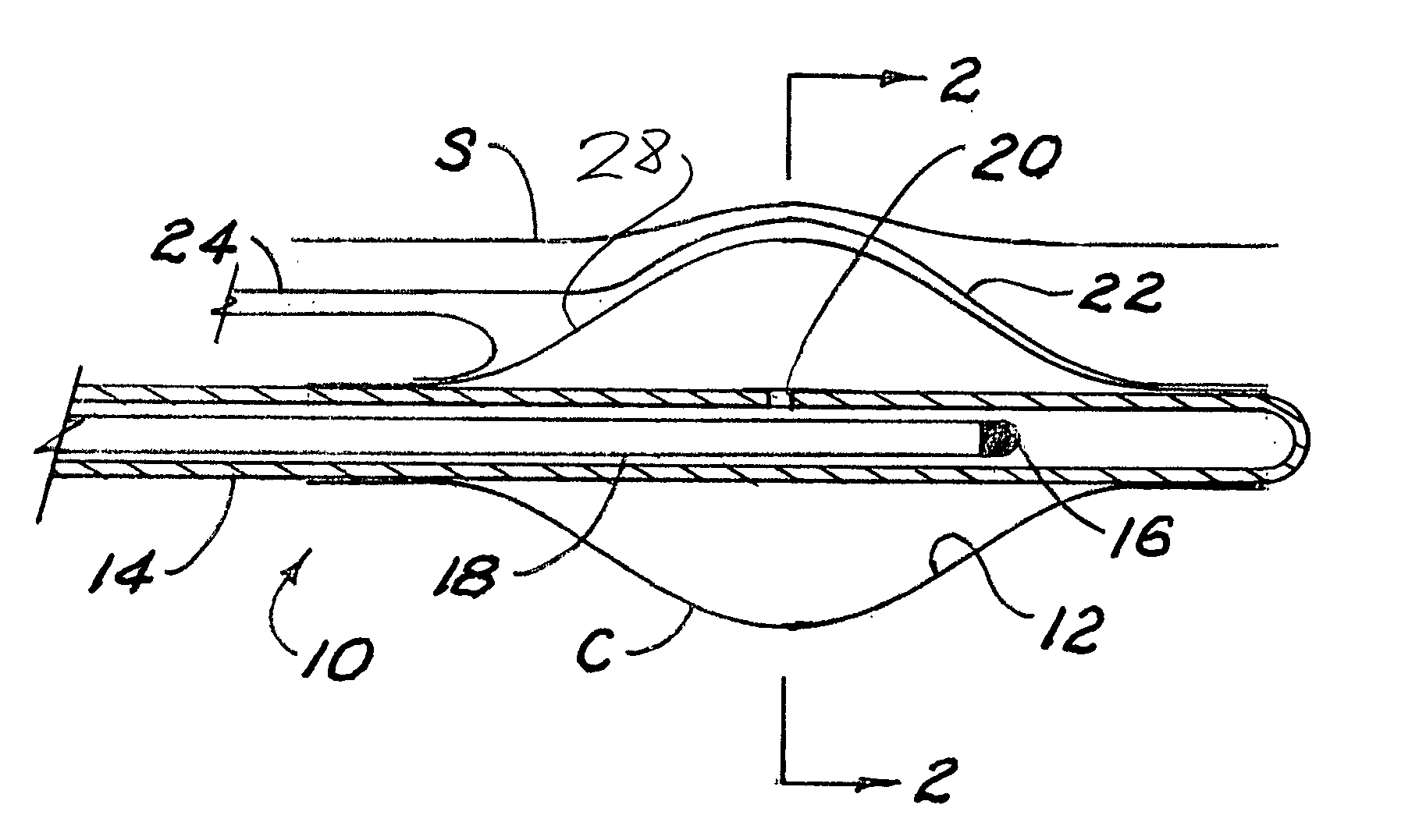
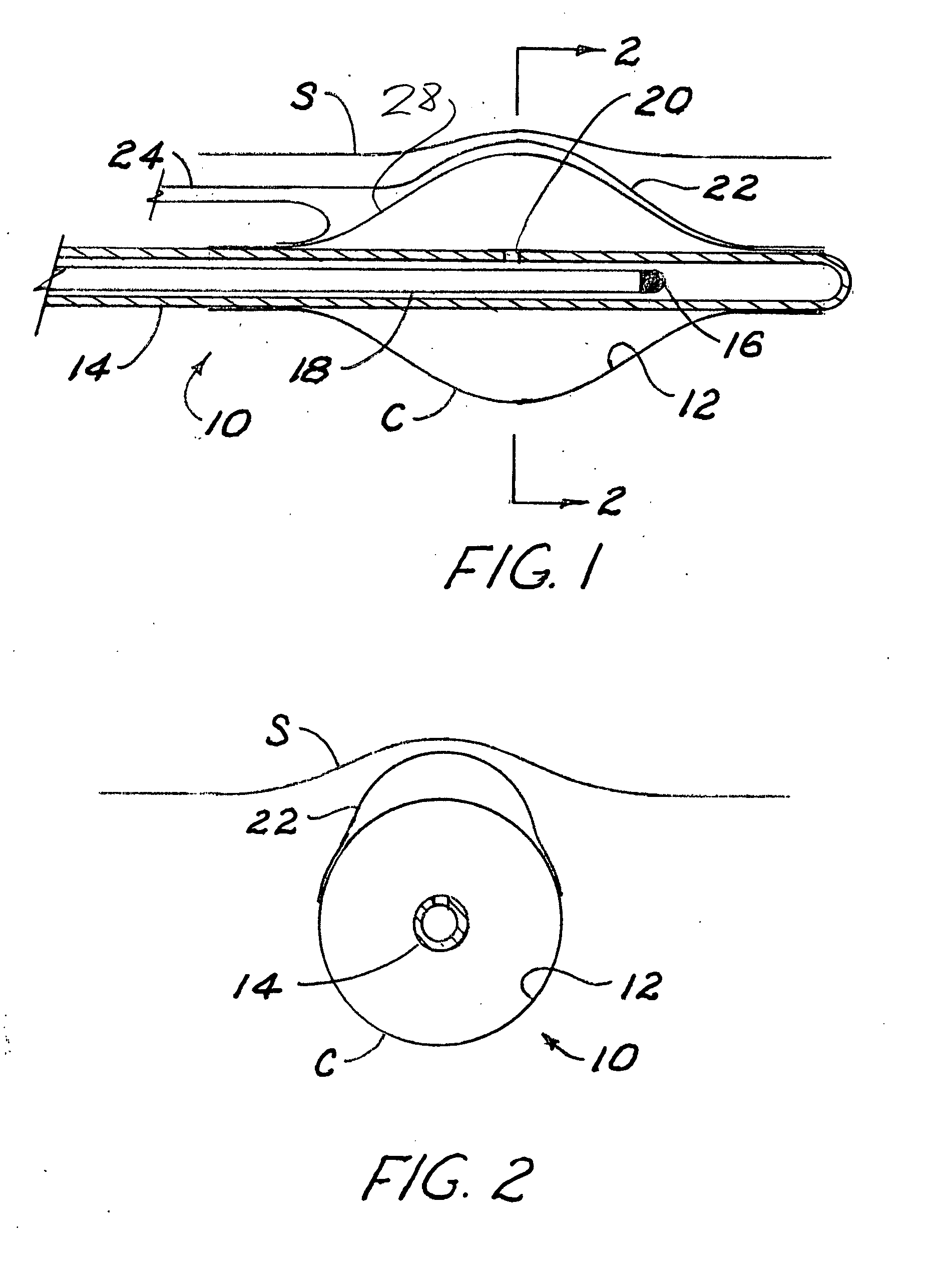
[0008]The balloons of the applicators of this invention are similar to those of existing applicators being axially symmetrical, facilitating positioning of the radiation source along the balloon axis, and which produce or tend to produce a desired cavity shape for isotropic brachytherapy upon inflation. In addition, however, the applicators of this invention may comprise at least one secondary balloon, preferably attached to a portion of the surface of the primary balloon in a manner wherein a substantial portion, often half of the secondary balloon surface (before inflation), is shared in common with the portion of the primary balloon surface to which it is attached, appearing in a form not unlike a blister. An alternate applicator system might comprise two (or more) independent balloons positioned to create the same spatial arrangement. Still another embodiment has a single balloon, but with a patch or area on one side that is substantially more flexibly elastic than the remaining balloon wall, so that once the balloon is fully inflated to a regular shape, further pressure can be added to blister out the flexible area.
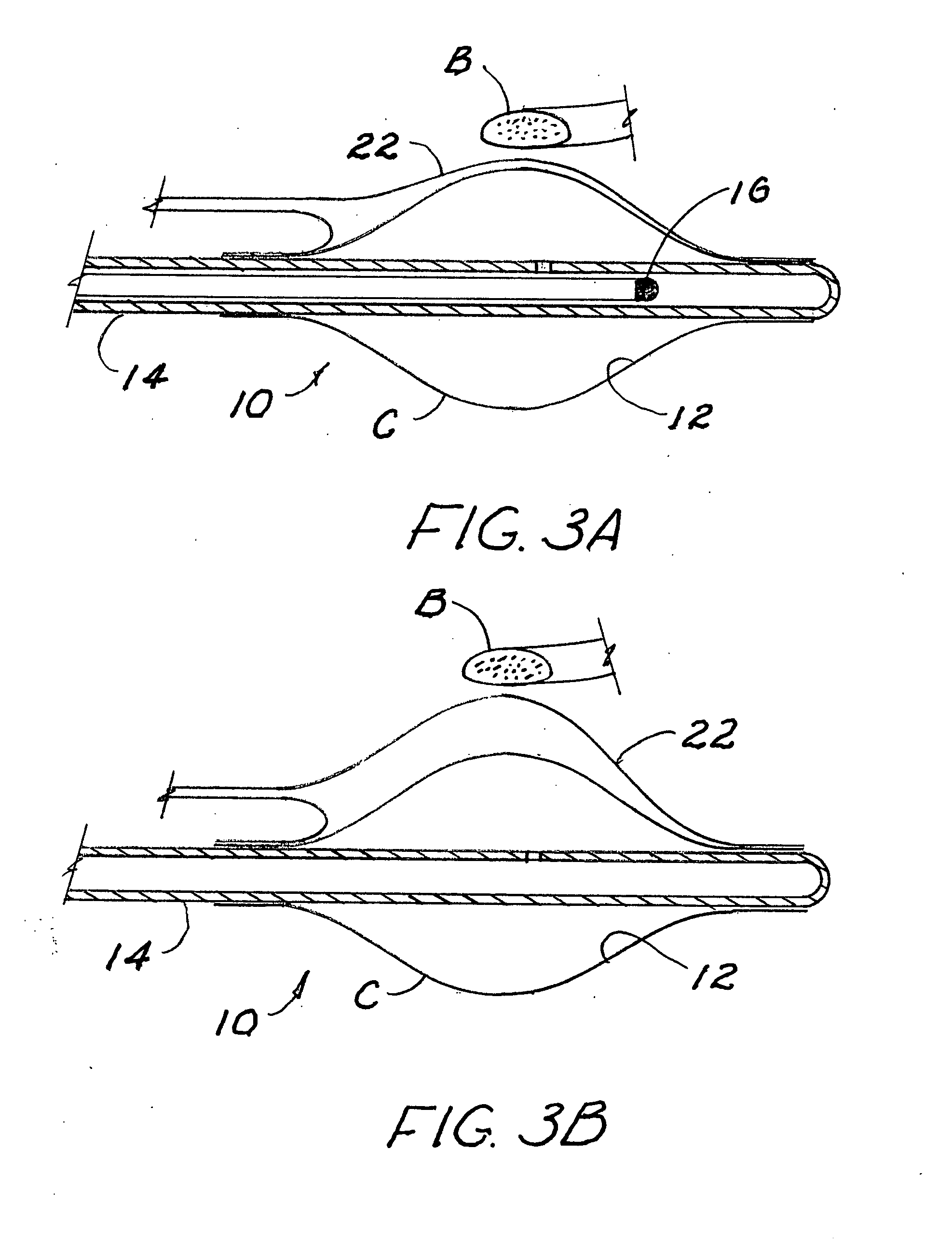
[0011]As described above, brachytherapy situations often arise in which the range of target tissue includes sensitive structures which might be at risk if subjected to a prescription dose or greater. In a preferred embodiment, a secondary balloon on the surface of the primary balloon may be oriented toward the at-risk structure when the applicator is placed within the body cavity. As the primary balloon is inflated, the orientation of the secondary balloon is maintained such that after completion of primary inflation which generally shapes the body cavity for brachytherapy, the secondary balloon may be inflated, increasing the distance locally between the radiation source in its guide tube and the at-risk structure. If inflation of the secondary balloon is carried to an extreme, at least in soft tissue, the prescription points adjacent to such structure would actually be brought into the secondary balloon volume. In practice, however, it is preferred that inflation of the secondary balloon only proceed until the at-risk structure is within safe radiation limits such that intervening tissue nearer the source receive as much dose as possible—ideally between the full and 2.5-3 times the full prescription dose, the latter at the cavity surface. As stated previously, the preferred inflation fluid in both balloons should have the radiation attenuation characteristics of water so as to simplify dose planning.
[0012]It is important that inflation of the secondary balloon not create air voids between the applicator and cavity near the creases or boundaries where the secondary balloon attaches to the primary balloon. Any such tendency to voids can be mitigated by use of secondary balloons that are more elastic relative to the more inelastic behavior of the primary balloon. Alternatively, surface channels and suction through suction lumina can be used to both eliminate voids between the cavity and balloons and withdraw seroma or other fluids. Generally, it is also important that the inflation pressure within the primary balloon be sufficient to prevent the common portion of the balloon surfaces from substantial intrusion into the interior space of the primary balloon as the secondary balloon is inflated. In an alternative method, however, the degrees of inflation may be balanced such that the intrusion of the secondary balloon into the volume of the primary balloon is substantial, perhaps even sufficient to displace the radiation source guide tube at the center of the primary balloon. This too would have the effect of increasing the distance from the source to the at-risk structure, but by bending the guide tube, the dose planning process may become more complicated.
[0018]Although the embodiments described above assume only one secondary balloon, the principles described above may be used to fashion applicators which can be used to protect one or more sensitive structures with multiple secondary balloons during administration of brachytherapy without unduly complicating the dose planning process, thus making brachytherapy a viable treatment option where it would not be with traditional applicators. Furthermore, by judicious choice of direction in which the applicator is inserted into the treatment cavity, a wide variety of complex structure situations can be accommodated with only a few applicator models having one, or at most two secondary balloons. An applicator with two secondary balloons might be used, for example, to protect bone adjacent one side and skin adjacent another side.

Problems solved by technology

If inflated sufficiently, such an elastic balloon may tend to enlarge the cavity overall in keeping with the mechanical resistance of the tissue it encounters, but in general it is so weak as to be incapable of producing predetermined features in the cavity or its surface with any degree of accuracy.

Method used


Image

  • Method and apparatus for modifying distance from a brachytherapy radiation source to sensitive anatomical structures
  • Method and apparatus for modifying distance from a brachytherapy radiation source to sensitive anatomical structures
  • Method and apparatus for modifying distance from a brachytherapy radiation source to sensitive anatomical structures

Examples


Embodiment Construction

[0030]In the drawing figures and the descriptions which follow, the balloons of the applicator embodiment are shown and described schematically in that balloon walls and membranes are generally represented by one line. It is preferable that the balloons be inflated with water or water-like liquid as described above. In addition to simplifying dose planning, control of inflated shapes can be substantially obtained by filling each chamber to a specified volume. Alternatively, however, inflation can be by gaseous medium with the desired shape control obtained by pressure control, perhaps verified by conventional imaging techniques, including x-ray where the balloon element materials are doped with radio-opaque fillers like barium sulfate or bismuth bicarbonate to enhance their display on x-ray film.

[0031]FIG. 1 schematically shows in section, an applicator 10 having a primary balloon 12 with a concentric radiation source guide tube 14 having a radiation source 16 inside, mounted on the...


PUM


Abstract

A balloon brachytherapy applicator has either a single or double chambers, with the capability of “blistering” outwardly at a specified area on one side of the balloon. This is useful to move sensitive tissue, such as skin or bone, farther away from a radiation source within a source guide inside the balloon. In one case a secondary balloon or secondary compartment is formed on the primary balloon, and is separately inflatable so as to allow blistering as desired when needed. In another form the balloon comprises a single chamber, primarily of inelastic or fairly rigidly elastic wall material, but with a “window” or area in which the balloon wall is elastic, or substantially more elastic than the main balloon wall, so that inflation of the balloon up to a certain point forms a substantially regular balloon shape (which may be approximately spherical), and the addition of further pressure will blister out the elastic area to increase the distance between the shaft and the sensitive tissue in a desired orientation of the balloon.

Description

BACKGROUND OF THE INVENTION[0001]This invention concerns radiation therapy, especially brachytherapy, for treating tissues which may have diffuse proliferative disease.[0002]In brachytherapy, the radiation source is generally placed within a surgically created or naturally occurring cavity in the body. In particular, this invention relates to delivery of radiation therapy to tissue as might be found in the human breast, or to other tissue, often following surgical treatment of cancer.[0003]Radiation therapy following tumor resection or partial resection is generally administered over a period of time in partial doses, or fractions, the sum of which comprises a total prescribed dose. This fractional application takes advantage of cell recovery differences between normal and cancerous tissue whereby normal tissue tends to recover between fractions, while cancerous tissue tends not to recover.[0004]In brachytherapy, a prescribed dose is selected by the therapist to be administered to a...

Claims


Application Information

Patent Timeline
IPC IPC(8): A61M36/06
CPCA61B2017/22069A61M25/1002A61N5/1015A61M2025/1061A61M25/1011
Inventor AXELROD, STEVEJERVIS, JAMES E.LOVOI, PAUL A.
Owner XOFT INC
Learn More