[0040] Certain embodiments of the present invention will be described in greater detail with reference to the accompanying drawings.
[0041] In the following description, like drawing reference numerals are used for the same elements even in different drawings. The matters defined in the description such as a detailed construction and elements are provided to assist in a comprehensive understanding of the invention. Thus, it is apparent that the present invention can be carried out without those defined matters. Also, well-known functions or constructions are not described in detail since they would unnecessarily obscure understanding of the invention.
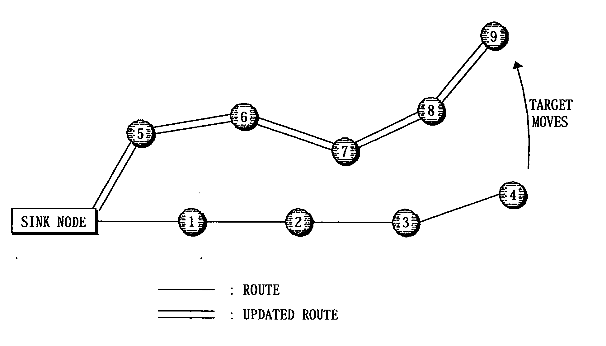
[0042]FIG. 9 shows one exemplary embodiment where a route is re-established according to the present invention. Briefly put, the present invention proposes an efficient way of re-routing using an existing route. The present invention further proposes an efficient way of re-routing by using only the sensor nodes within a predetermined range with respect to a sensor node on the existing route. According to the embodiment of the present invention as shown in FIG. 9, when a sensor node collecting information of the target changes due to movement of the target, the route is updated. The new route uses the nodes within one hop from the old route. By this route updating method, the number of nodes required for the re-routing can be reduced, and a reduced number of messages are used. Although the present embodiment depicts the example where the route update is performed according to the movement of the target, one will appreciate that update may also be performed when the sink node moves, or when both the sink node and the target move.
[0043] The present invention will now be described in greater detail, with reference to two main stages of the route update process. First, the first stage of route update will be described:
[0044] The First Stage
[0045] Route update according to one embodiment of the present invention will be described mainly with reference to FIG. 10 which illustrates re-routing according to one embodiment of the present invention.
[0046]FIG. 10 shows the sensor nodes which collect information of a moving target and transmit the collected information to the sink node. The sensor node detects the target only when the target stays inside the sensing range. The sensor node 1 has a sensing range 1000, and the sensor node 2 has a sensing range 1002. The sensor node 3 has a sensing range 1004. Although FIG. 10 shows an individual sensing range for each sensor node, one of ordinary skill in the art will appreciate that the present invention is also applicable to a case where the sensing ranges of the sensor nodes overlap. It is assumed that the target, which was inside the sensing range 1000, passes the sensing range 1002, and moves to the sensing range 1004. Using the old route when it was within the sensing range 1000, the sensor node 1 transmits information of the target to the sensor node 4. The sensor node 1 can transmit its data through a transmission area 1010. Because the sensor node 4 is within the transmission range 1010, it can receive the data from the sensor node 1. The sensor node 4 then transmits received data to the sensor node 5 through a preset route.
[0047] If the target moves from the sensing range 1000 to the sensing range 1002, due to the movement of the target, the sensor node 1 can not sense the target anymore. Accordingly, the sensor node 1 broadcasts information about the target and information about the sensor node 4 at predetermined time intervals. Due to the movement of the target, the sensor node 2 can now sense the target. The sensor node 2 also recognizes by the information broadcast from the sensor node 1 that it should transmit information about the target to the sensor node 4. The sensor node 4 deletes information about the sensor node 1 and the information about the hop count from the routing table. The sensor node 2, sensing the target, transmits a response to the sensor node 1. The sensor node 1 in receipt of the response stops the broadcasting of information about the target and the information about the sensor node 4.
[0048] The sensor node 2 transmits a routing request message to the sensor node 4. Because the transmission range of the sensor node 2 is 1012, the sensor node 4 receives the routing request message from the sensor node 2. Using the routing request message as received, the sensor node 4 updates its routing table. The sensor node 4 transmits a routing response message to the sensor node 2. Using the received routing response message, the sensor node 2 generates a routing table regarding a new sensor node 2, thereby building a route to the sensor node 4. The sensor node 2 collects information about the target, and transmits the collecting information to the sensor node 4 using the set route.
[0049] If the target is moved from the sensing range 1002 to the sensing range 1004, the sensor node 2 operates in the same way as the sensor node 1. The sensor node 3 transmits a routing request message to the sensor node 4. Because the transmission range of the sensor node 3 is 1014, the sensor node 4 can not receive the routing request message from the sensor node 3. Accordingly, the sensor node 4 enters into the second stage of the route update which will be described below.
[0050] The Second Stage
[0051] The second stage of the route update will be described in greater detail below with reference to FIG. 9 and one certain embodiment of the present invention.
[0052] The sensor node 4 transmits information about the target to the sink node, using a set route. The target moves from the sensing range of the sensor node 4 to the sensing range of the sensor node 9. The sensor node 4 can not collect information of the target anymore, and therefore, operates in the same way as in the first stage described above. Meanwhile, the sensor node 3 is without the transmission range of the sensor node 9. Accordingly, the sensor node 9 can not receive a routing response message from the sensor node 3. Having not received the routing response message, the sensor node 9 broadcasts a routing request message. The routing request message is received at the sensor node 8 and the sensor node 4, respectively. The sensor node 8 and the sensor node 4, in receipt of the routing request message, update their routing tables, respectively. The updated routing table includes a hop count for the received routing request message. The hop count is, for example, set to ‘1’.
[0053] If a routing request message is not received for a predetermined time, the sensor node 3 broadcasts a routing request message including an infinite hop count. The sensor node 4, the sensor node 8, the sensor node 2 and the sensor node 7 receive the routing request message, respectively. The sensor node 2 infinitely updates the hop count of the routing table. The sensor node 7 stores the routing table which includes the infinite hop count. The sensor node 8 compares the hop count contained in the received routing request message with the hop count of the routing table. If the comparison results indicate that the hop count of the routing table is smaller than the hop count of the routing request message, the sensor node 8 generates a routing request message. The sensor node 8 broadcasts the generated routing request message to the neighboring sensor nodes. If the comparison result indicates that the hop count of the routing table is larger than the hop count of the routing request message, the sensor node 8 stops broadcasting. FIG. 9 shows one example where the hop count of the routing table is set to ‘1’, and the hop count of the routing request message being infinite.
[0054] The sensor node 7, in receipt of the routing request message broadcast from the sensor node 8, updates its routing table. Using the received routing request message, the sensor node 3 updates its routing table. The sensor node 3 transmits a routing revise RREV message to the sensor node 2. The RREV message contains a hop count. The sensor node 2 performs the operations by the sensor node 3, and the sensor node 7 performs the operation by the sensor node 8. The sensor node 1 performs the operation by the sensor node 3, and the sensor node 6 performs the operation by the sensor node 8. The sensor node 5, in receipt of the routing request message from the sensor node 6, updates its routing table and transmits a routing request message to the sink node. The sensor node 1 transmits RREV message to the sink node. The sink node receives a routing request message and RREV message from the sensor node, 5 and the sensor node 1, respectively, and compares the received messages, selects the one having less hop count and transmits a routing response message accordingly. If the hop counts are determined to be equal, the sink node selects a new route. FIG. 9 shows one example where the sink node transmits a routing response message through a new route, i.e., to the sensor node 5, when the hop counts are determined to be equal. By the above processes, a new route is built between the sink node and the sensor node 9.
[0055] Instead of using a route which connects the old route and the sensor node 9, data is transmitted through a new route which has the same hop counts. As a result, a new route can be efficiently established when the target moves. Additionally, because sensor nodes within 1 hop area participate in the update of route, the number of messages transmitted among the nodes can be reduced. If necessary, sensor nodes at a 2-hop distance or within a certain number of hops can participate in the re-routing.
[0056]FIG. 11 shows the operation of a certain sensor node which is positioned on an old route. This sensor node on the old route will hereinbelow called “NR”, and the sensor nodes within 1-hop distance from the old route will be called “NN” for the convenience of explanation.
[0057] In operation S1100, NR receives PREQ or RREV. In operation S1102, NR updates its routing table, using the received RREQ or RREV. In operation S1104, NR determines whether the received message is RREQ or not. If so, the operation S1106 is performed, and if not, the operation S1108 is performed. The NR in the operation S1108 generates a RREQ and broadcasts the generated RREQ. In operation S1106, NR determines whether its routing table is updated. If so, the operation S1110 is performed, and if not, the operation S1118 is performed.
[0058] In operation S1110, NR determines whether RREQ is received from NN or not. If so, the operation S1112 is performed, and if not, the operation S1118 is performed. In operation S1112, NR determines whether the sensor node is a fixed destination sensor node, i.e., determines whether it is the sink node or not. If so, the operation S1114 is performed, and if not, the operation S1116 is performed. In operation S1114, NR generates a RREP, and transmits the generated RREP. In operation S1116, NR transmits RREV to the neighboring NR.
[0059]FIG. 12 shows the operation at NN. In operation S1200, NN receives RREQ. In operation S1202, NN updates its routing table by using received RREQ. In operation S1204, NN determines whether its routing table is updated. If so, the operation S1206 is performed, and if not, the operation S1212 is performed.
[0060] In operation S1206, NN determines whether RREQ is received from NR or not. If so, the operation S1208 is performed, and if not, the operation S1212 is performed. In operation S1208, NN compares the hop count of its routing table with that of the received RREQ. If a comparison result indicates that the hop count of received RREQ is larger, the operation S1210 is performed, and if not, the operation S1212 is performed. In operation S1210, NN generates a RREQ by using its routing table, and broadcasts the generated RREQ.
[0061]FIG. 12 does not illustrate RREP. The NN transmits the received RREP to the neighboring sensor node by using its routing table. That is, NN transmits a message either to a neighboring NN or a neighboring NR according to the comparison of hop counts.
[0062] Although FIG. 9 depicts one example where the target moves, one of ordinary skill in the art will appreciate that the present invention is also applicable to a case where the sink node moves.
[0063] As described above in a the exemplary embodiments of the present invention, a new route is established by using sensor nodes within a predetermined distance from the old route, and therefore, the number of transmitted messages can be reduced. Additionally, by efficiently updating a route in accordance with the movement of the target, a power consumption of the sensor nodes of the sensor network can be reduced.
[0064] The foregoing embodiment and advantages are merely exemplary and are not to be construed as limiting the present invention. The present teaching can be readily applied to other types of apparatuses. Also, the description of the embodiments of the present invention is intended to be illustrative, and not to limit the scope of the claims, and many alternatives, modifications, and variations will be apparent to those skilled in the art.