Noise reducing device

a noise reduction and noise technology, applied in the direction of sound producing devices, electrical transducers, instruments, etc., can solve the problems of large social problems, large noise reduction effect, and large noise reduction

Inactive Publication Date: 2005-07-21
TAKENAKA KOMUTEN CO LTD
View PDF1 Cites 18 Cited by
  • Summary
  • Abstract
  • Description
  • Claims
  • Application Information

AI Technical Summary

Benefits of technology

[0029] As described above, according to the invention, in an active control type noise reducing device added to a sound barrier, a control sound can be emitted in the same direction as the incident direction of noise, and noise made incident at the sound barrier from a predetermined direction can be effectively reduced. Namely, there is the effect that an excellent noise...

Problems solved by technology

Motorcycles of motorcycle gangs also travel on these roadways spreading loud explosive noise.
The problem of road traffic noise is becoming manifest not only in urban areas but also in rural areas and has become a large social problem.
However, an ASE sound barrier only exhibits a noise reducing effect in the vicinity of the upper surface of an ASH cell that is the...

Method used


Image

  • Noise reducing device
  • Noise reducing device
  • Noise reducing device

Examples


first embodiment

(Noise Reduction Control Zone)

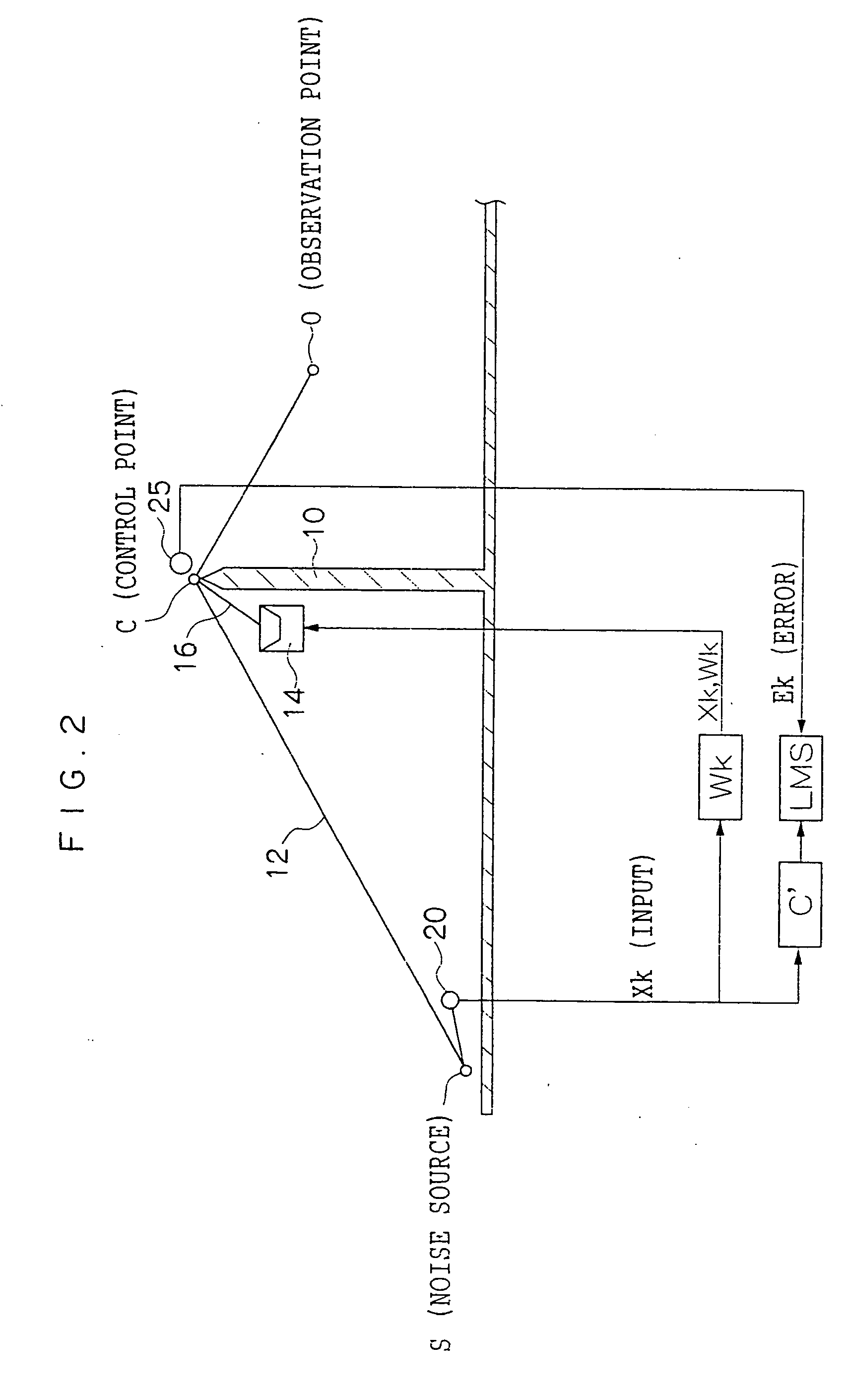
[0053] In the present embodiment, as shown in FIG. 3A, sound barriers 10 of a predetermined height are disposed at both sides of an expressway 100 parallel to the road in order to reduce noise emitted from an automobile that is a noise source S. The sound barriers 10 are configured by metal panels such as iron panels that are disposed vertically with respect to the road surface. It should be noted that noise reducing reinforcement panels may also be disposed at the noise source S sides of the sound barriers 10. It is preferable for the noise reducing reinforcement panels themselves to have a bass noise reducing capability of at least 10 dB. For example, a panel where a noise absorbing material such as a glass wall is adhered to the panel surfaces at the noise source S sides can be appropriately used.

[0054] When an observation point O is set at the outer side of the sound barriers 10, noise propagates from various directions to the observation point O...

second embodiment

[0093] A traffic noise reducing system pertaining to a second embodiment has the same configuration as that of the first embodiment, except that the noise control units of the second embodiment are configured to include a single sound source microphone and plural speaker units. Therefore, description of identical portions will be omitted and only the points of difference will be described.

[0094] The noise control units of the present embodiment are plurally disposed along sound barriers. Because the configurations of the noise control units are the same, one noise control unit will be described. As shown in FIG. 15, a noise control unit 104 is disposed at the sound source side of the sound barrier 10 and includes plural (three in the drawing) speaker units 141 to 143 and a single sound source microphone 20a.

[0095] The speaker units 141 to 143 are arranged at predetermined intervals along the sound barrier 10 and respectively include speaker arrays 401 to 403 in which plural (nine ...

third embodiment

[0107] A traffic noise reducing system pertaining to a third embodiment has the same configuration as that of the first embodiment, except that the noise control units of the third embodiment are configured to include a single sound source microphone and plural speaker units. Therefore, description of identical portions will be omitted and only the points of difference will be described.

[0108] As shown in FIG. 17, a noise control unit 106 includes plural (three in the drawing) speaker units 144 to 146 and a single sound source microphone 20b disposed at the noise source side of the sound barrier 10. The speaker units 144 to 146 are arranged at predetermined intervals along the sound barrier 10 and respectively include speaker arrays 404 to 406 in which plural (nine in the drawing) linear array of flat loudspeakers are avenged in one row along the sound barrier 10. The sound source microphone 20b is disposed at the incoming side of the automobiles with respect to the speaker unit 14...


PUM


Abstract

The present invention provides an active control type noise reducing device that is disposed at a sound barrier and with which can be obtained an excellent noise reduction effect with respect to moving sound sources. Linear array of flat loudspeakers are arranged in ascending order from an incoming side of automobiles towards an outgoing side. Delay times of 0, τ, 2τ, . . . , 8τ are respectively given in the arrangement order to the linear array of flat loudspeakers. By delaying signals in correspondence to the arrangement order, the wavefront of a control sound can be slanted in a diagonal direction. Namely, “line sound sources”, where sound sources are linearly arranged, arc pseudo-realized.

Description

CROSS-REFERENCE TO RELATED APPLICATIONS [0001] This application claims priority under 35 USC 119 from Japanese Patent Application No. 2003-136698, the disclosure of which is incorporated by reference herein. BACKGROUND OF THE INVENTION [0002] 1. Field of the Invention [0003] The present invention relates to a noise reducing device, and in particular to an active control type noise reducing device that is added to a sound barrier and reduces noise by active control. [0004] 2. Description of the Related Art [0005] In Japan, roadways pass through residential areas and alongside hospitals that are supposed to be quiet, and large trucks come and go through these roadways day and night. Motorcycles of motorcycle gangs also travel on these roadways spreading loud explosive noise. The problem of road traffic noise is becoming manifest not only in urban areas but also in rural areas and has become a large social problem. [0006] In recent years, a system called active noise control (ANC) that...

Claims


Application Information

Patent Timeline
IPC IPC(8): G10K11/178E01F8/00
CPCG10K11/178G10K11/17861G10K11/17857G10K11/17881G10K11/17853
Inventor NAKAJIMA, TATSUMISUZUKI, KAZUNORI
Owner TAKENAKA KOMUTEN CO LTD
Why Eureka
Try Eureka