Image forming method and image forming apparatus

a technology of image forming and forming method, which is applied in the direction of electrographic process apparatus, geometric image transformation, instruments, etc., can solve the problems of inability to arrange the direction of the image that facilitates the stapling apparatus is expensive, and the staple mechanism is complicated, so as to facilitate the removal of the transfer sheet and smooth operation

Active Publication Date: 2005-07-21
KONICA MINOLTA BUSINESS TECH INC
View PDF3 Cites 8 Cited by
  • Summary
  • Abstract
  • Description
  • Claims
  • Application Information

AI Technical Summary

Benefits of technology

[0047] wherein the image rotation control for finish processing has precedence-over the image rotation control for removal of the sheet. This arrangement provides a simple structure capable of forming an image, with consideration given to ensuring such a direction of the image as to facilitate removal of the transfer sheet, and allows complete processing of finishing where the direction is specified.
[0048] (5) Control is provided such a way as to select and feed the transfer sheet having the direction conforming to the direction in ejection, the direction of removing the transfer sheet or the direction of finishing, whereby ensuring smooth operation of each of the aforementioned control items:

Problems solved by technology

To provide an apparatus capable of stapling at any one of the four corners or edges, the staple mechanism is complicated and the stapling apparatus is costly.
However, it fails to arrange the direction of the image that facilitates removal of the transfer sheet.
It fails to provide the direction of the image that facilitates the re-setting of a bundle of transfer sheets on another finisher (#1) or to the removal of the bundle of transfer sheet.

Method used


Image

  • Image forming method and image forming apparatus
  • Image forming method and image forming apparatus
  • Image forming method and image forming apparatus

Examples


Embodiment Construction

[0064] Referring to drawings, the following describes the details of the best form (hereinafter referred to as “embodiment”) of the present invention.

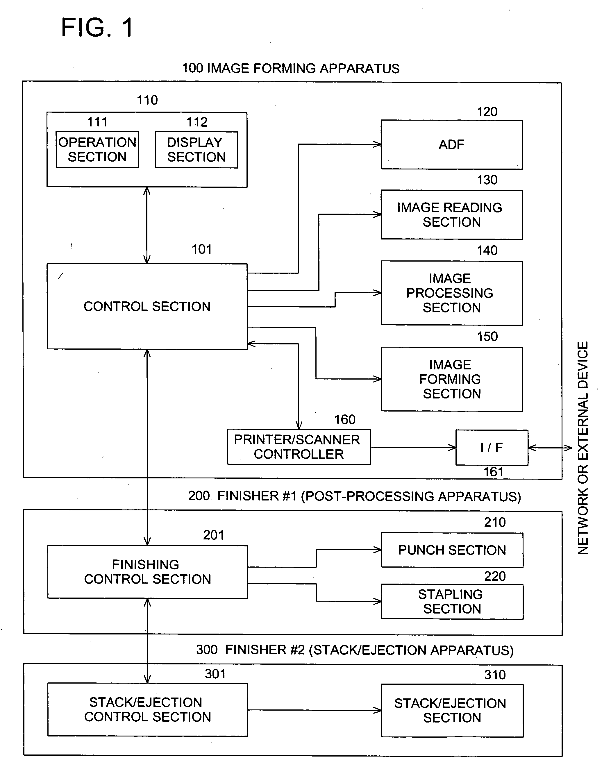
[0065]FIG. 1 is a functional block diagram representing an example of the electric configuration between the image forming apparatus 100 in an embodiment of the present invention and finisher (#1) connected thereto.

[0066] To give a specific description of the embodiment, an image forming apparatus such as a copying machine equipped with an image reading section ill be used as an example for explanation. The same operation and effect are provided by using an image forming apparatus without an image reading section such as a printer.

[0067] In FIG. 1, numeral 100 denotes an image forming apparatus composed of the following sections. Numeral 101 is a control section as a control means for controlling each part of the image forming apparatus 100. Numeral 110 indicates an operation / display section 110 consisting of an operation section 11...


PUM


Abstract

There is described an image forming apparatus combined with a finisher for applying finish processing such as stapling. The image-forming apparatus includes: a reading section to read an original image so as to generate image data of the original image; a designating section to designate a first direction of the original image to be read by the reading section and a second direction of an output image to be ejected; an image-processing section to apply image-processing, which includes an image-rotation processing, to the image data so as to generate processed image data; a controlling section to control a rotation angle to be employed for rotating the image data by the image-rotation processing, referring to the first direction and the second direction, so that a direction of the output image coincides with the second direction; and an image-forming section to form the output image based on the processed image data.

Description

BACKGROUND OF THE INVENTION [0001] The present invention relates to an image forming method and image forming apparatus, particularly to an image forming method and image forming apparatus when the image forming apparatus is connected with a finisher (#1) for applying processing of finishing such as stapling. [0002] When images of a plurality of documents have been formed by an image forming apparatus such as a copying machine, sheets are collated for each copy and are bound by stapling (staple-finishing) in some cases. [0003] In this case, a finisher (#1) is placed adjacent to the image forming apparatus proper and the transfer sheet ejected from the image forming apparatus proper is received by the finisher (#1), which applies processing of staple-finishing. [0004] When such staple finishing is performed, one of the four corners of the document is specified if one-point binding (corner stapling) is used. When two-point binding (lateral stapling) is used, any one of four edges is s...

Claims


Application Information

Patent Timeline
Patent Type & Authority Applications(United States)
IPC IPC(8): G03G15/00G03G21/00G03G15/36G06T3/60H04N1/387
CPCG03G15/5025H04N1/00631H04N2201/0091H04N1/3871H04N1/3877H04N1/00639
Inventor NAKAMURA, SHOICHIUSHIO, MASARUKUROHATA, TAKAO
Owner KONICA MINOLTA BUSINESS TECH INC
Why Eureka
Try Eureka