Look-ahead predicate generation for join costing and optimization

a predicate and join costing technology, applied in the field of look-ahead predicate generation for join costing and optimization, can solve the problems of inability to reliably identify many known methods, extreme inefficiency of conventional oltp methodology,

Inactive Publication Date: 2005-07-21
IBM CORP
View PDF2 Cites 23 Cited by
  • Summary
  • Abstract
  • Description
  • Claims
  • Application Information

AI Technical Summary

Benefits of technology

[0010] Unfortunately, known methods cannot reliably identify many situations where a “star join” method should be substituted for a conventional inner / outer join, for the reason that business intelligence database schema often do not follow a conventional star pattern. Rather, in some instances the schema for a business intelligence database has a more complex, “snowflake” pattern such as is shown in FIG. 2A.

Problems solved by technology

The challenge inherent in such queries is that the conventional online transaction processing (OLTP) implementation of the join operations, would treat the Sales table as the inner table of one or both of the joins; that is, for example, the join of the SKU table and Sales table would be performed by reviewing each row (tuple) in the SKU table, and for each matching SKU, reviewing the entire Sales table for matching sales.
Where the Sales table expands to the terabyte size mentioned above, this conventional OLTP methodology becomes extremely inefficient.
Unfortunately, known methods cannot reliably identify many situations where a “star join” method should be substituted for a conventional inner / outer join, for the reason that business intelligence database schema often do not follow a conventional star pattern.
The key difficulty with databases having a “snowflake” or other complex schema is that techniques used to determine when to use a star join and when to use a conventional inner / outer join, are specialized and are applicable only to schema that fit a specific typical or expected schema.

Method used


Image

  • Look-ahead predicate generation for join costing and optimization
  • Look-ahead predicate generation for join costing and optimization
  • Look-ahead predicate generation for join costing and optimization

Examples


Embodiment Construction

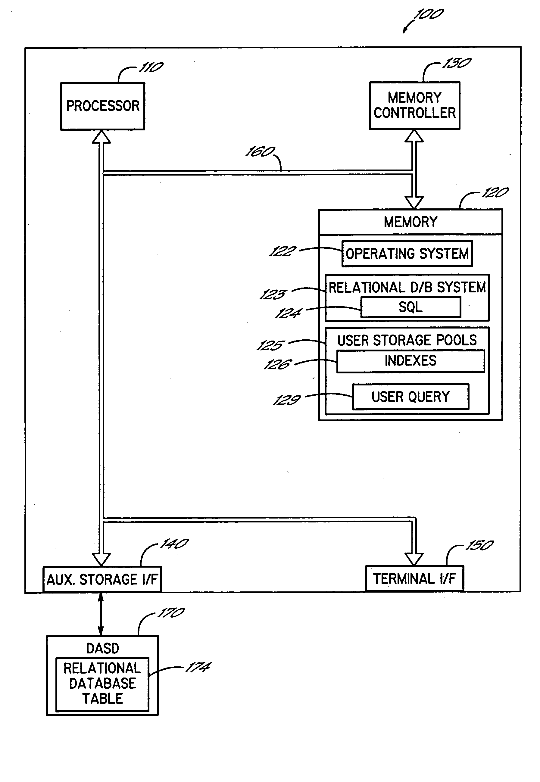
[0023] The methods of the present invention employ computer-implemented routines to query information from a database. Referring now to FIG. 3, a block diagram of a computer system which can implement an embodiment of the present invention is shown. The computer system shown in FIG. 3 has a particular configuration; however, those skilled in the art will appreciate that the method and apparatus of the present invention apply equally to any computer system, regardless of whether the computer system is a complicated multi-user computing apparatus or a single user device such as a personal computer or workstation. Thus, computer system 100 can comprise other types of computers such as IBM compatible personal computers running OS / 2 or Microsoft's Windows. Computer system 100 suitably comprises a processor 110, main memory 120, a memory controller 130, an auxiliary storage interface 140, and a terminal interface 150, all of which are interconnected via a system bus 160. Note that various...


PUM


Abstract

A relational database system analyzes each potential join in a query, to determine whether a relation involved in the join is subject to a selection criterion, and evaluate whether that selection criterion or the join per se effects a join reduction. The computational expense of generating a look-ahead predicate comprising the tuples of the second relation matching any applicable selection criterion, is compared to the computational savings that result from the join reduction. The most beneficial look-ahead predicate among all potential joins of relations in the query is identified through iterative analysis of all possible joins. Thereafter, membership in the look-ahead predicate is added as a selection criterion on the first relation, and further iterative analysis is performed of all possible joins of the remaining relations and the look-ahead predicate, to iteratively identify additional joins in the query that benefit from the formation of the look-ahead predicate, and potentially form further look-ahead predicates.

Description

FIELD OF THE INVENTION [0001] The present invention relates to generation of join query results in the management and execution of relational database queries. BACKGROUND OF THE INVENTION [0002] Relational Database Management System (RDBMS) software using a Structured Query Language (SQL) interface is well known in the art. The SQL interface has evolved into a standard language for RDBMS software and has been adopted as such by both the American Nationals Standard Organization (ANSI) and the International Standards Organization (ISO). [0003] In RDBMS software, all data is externally structured into relations, each relation dealing with one or more attributes and comprising one or more tuples of data, each tuple associating attribute values with each other. A relation can be visualized as a table, having rows and columns (indeed, the relations in a particular database are often referred to as the “tables” of the database). When a relation is visualized as a table, the columns of the ...

Claims


Application Information

Patent Timeline
Patent Type & Authority Applications(United States)
IPC IPC(8): G06F7/00G06F17/30
CPCG06F17/30498G06F16/2456
Inventor ABDO, ABDO ESMAILBESTGEN, ROBERT JOSEPHDIETEL, JOHN DAVID
Owner IBM CORP
Why Eureka
Try Eureka