
System and method for scheduling the execution of model components using model events

a technology of model components and event scheduling, applied in the field of model component execution, can solve the problems of restricted scope of conditional execution, inability to execute various blocks distributed throughout the model, and inability to meet the requirements of the model

Active Publication Date: 2005-07-21
THE MATHWORKS INC
View PDF12 Cites 41 Cited by
  • Summary
  • Abstract
  • Description
  • Claims
  • Application Information

AI Technical Summary

Problems solved by technology

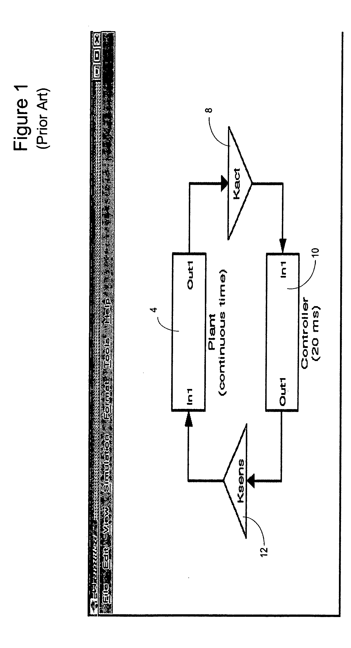
However, the scope of conditional execution is generally restricted to a subsystem as conventional methods of specifying the relationships do not allow the scope of conditional execution to be defined as an arbitrary set of blocks (as opposed to the set of blocks that comprise a subsystem).
This is a significant limitation, since there are times where it is desirable to simultaneously execute a set of blocks that are not in a subsystem and / or are not contiguous in the model.
For example, conventional methods of conditional execution do not allow execution of various blocks distributed throughout the model at power-up or power-down.
As a result, the manner in which the causal relationships may be composed is restricted.
Conventional methods of specifying the causal relationships between the dynamics of a model and the execution of model components do not allow a user to enable half of the blocks in a subsystem and trigger the other blocks.
An additional drawback to conventional mechanisms for specifying the causal relationships between the dynamics of a model and the execution of model components is that these mechanisms require graphical connections to be made in the block diagram to indicate causality.
This can result in an appearance which some users feel “clutters” the diagram.
Another limitation to conventional mechanisms for specifying causal relationships is that the conventional mechanisms do not naturally map to advanced software or operating system constructs, such as initialization, exceptions, or tasks.
Similarly, since conventional mechanisms of specifying the causal relationships lack a first class object associated with the causal relationship, it is difficult to configure and assign characteristics to that relationship.
It is also difficult for the user to directly leverage implicit dynamics associated with the mechanisms, for example the enable and disable methods associated with an enabled subsystem, and to conditionally execute components of the model based on these implicit dynamics.

Method used


Image

  • System and method for scheduling the execution of model components using model events
  • System and method for scheduling the execution of model components using model events
  • System and method for scheduling the execution of model components using model events

Examples


Embodiment Construction

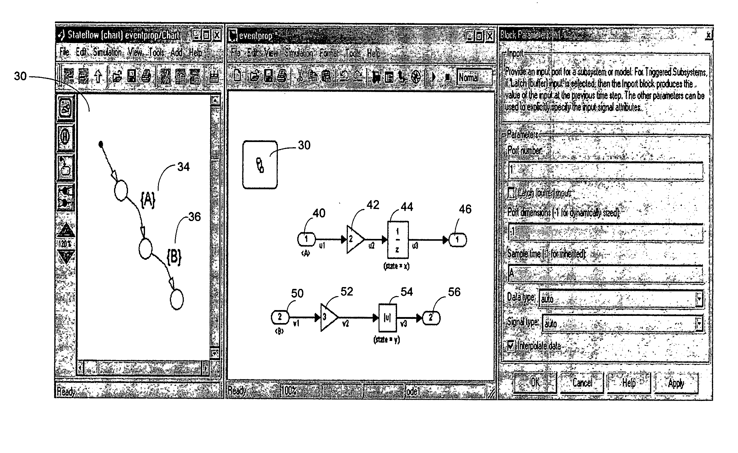
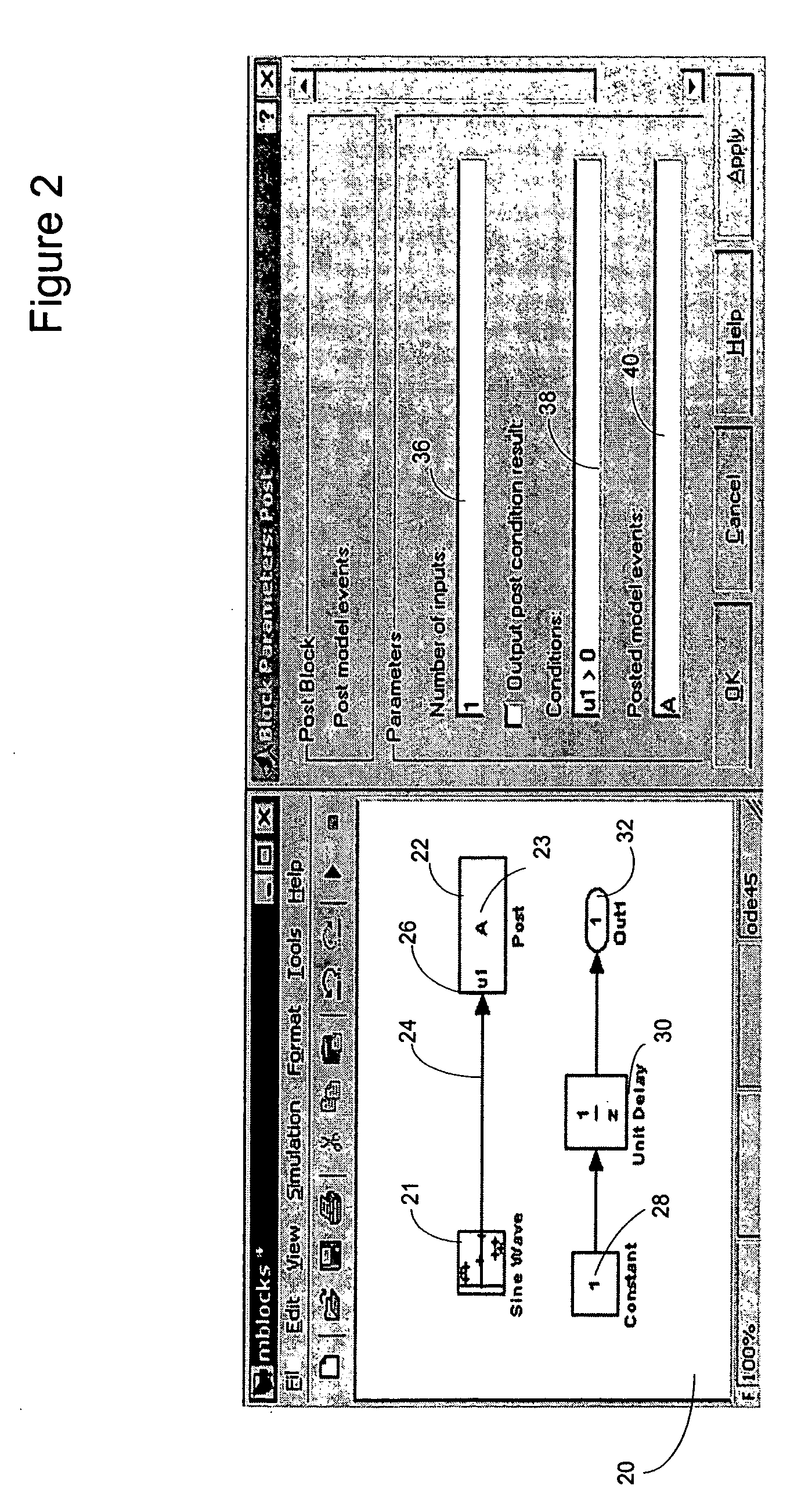
[0029] The illustrative embodiment of the present invention provides a mechanism for tying the execution of model components to the occurrence of specified model events. Sample rates are specified as events thus tying model component execution to the dynamics of the model. Non-contiguous model elements may be configured to conditionally execute based on model event occurrence. Additionally, the scope of component execution is not limited to subsystems in their entirety as is required by certain conventional systems. The conditional execution of components based on event occurrence may also be used for exception handling. Associations between model components and events may be established without drawing additional component connections in the view of the model.

[0030] For sake of clarity, the explanation of the illustrative embodiment of the present invention contained herein makes reference to a Simulink™ and MATLAB™-based modeling environment (both applications from The MathWorks ...


PUM


Abstract

A method of specifying and configuring a causal relationship between the dynamics of a graphical model and the execution of components of the model is disclosed. Model component execution is tied to the occurrence of model events. Model events are first defined in the modeling environment. The occurrence of conditions in the model specified in the definition of the event causes the event to be “posted”. Model components that have been associated with the occurrence of the event “receive” the notice of the posting of the event and then execute. Random components within a subsystem may be designated to execute upon the occurrence of an event, as may non-contiguous components within a model. The association between model events and component execution may be specified without drawing graphical indicators connecting components in the view of the model.

Description

RELATED APPLICATION [0001] The illustrative embodiment of the present invention is related to a presently pending U.S. patent application entitled, “A System and Method for Using Execution Contexts in Block Diagram Modeling”, Ser. No.: 10 / 414, 644, the contents of which are hereby incorporated by reference.FIELD OF THE INVENTION [0002] The illustrative embodiment of the present invention relates generally to the execution of model components within a modeling environment, and more specifically to the scheduling of the execution of modeling components using model events. BACKGROUND [0003] Simulink™ from The MathWorks, Inc. of Natick, Mass., is an example of a graphical modeling environment, specifically a block diagram environment. Simulink™ allows users to create a pictorial model of a dynamic system. The model consists of a set of symbols, called blocks. Each block can have zero or more input ports, output ports, and states. Each block represents a dynamic system whose inputs, stat...

Claims


Application Information

Patent Timeline
IPC IPC(8): G06F9/46G06F17/50
CPCG06F9/542G06F2209/543G06F2217/74G06F17/5009G06F30/20G06F2111/12G06F8/31
Inventor SZPAK, PETERENGLEHART, MATTHEW
Owner THE MATHWORKS INC
Learn More