Portable electric cutting apparatus

Active Publication Date: 2005-07-28
HITACHI KOKI CO LTD
View PDF15 Cites 25 Cited by
  • Summary
  • Abstract
  • Description
  • Claims
  • Application Information

AI Technical Summary

Benefits of technology

[0031] According to another aspect of the invention, the laser oscillator is placed at a position such that laser light emitted by the laser oscillator is applied onto the cutting extension of the cut material. By

Problems solved by technology

However, in the configuration of the portable circular saw in the related art described above, the groove 5b needs to be provided on the bottom of the base 5 and thus the strength of the base 5 is a little degraded; this is a pr

Method used


Image

  • Portable electric cutting apparatus
  • Portable electric cutting apparatus
  • Portable electric cutting apparatus

Examples


first embodiment

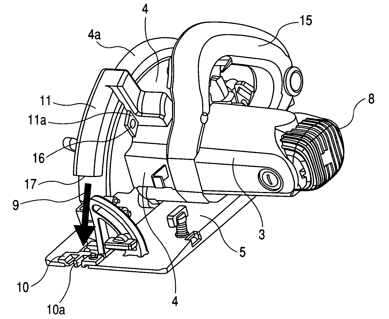
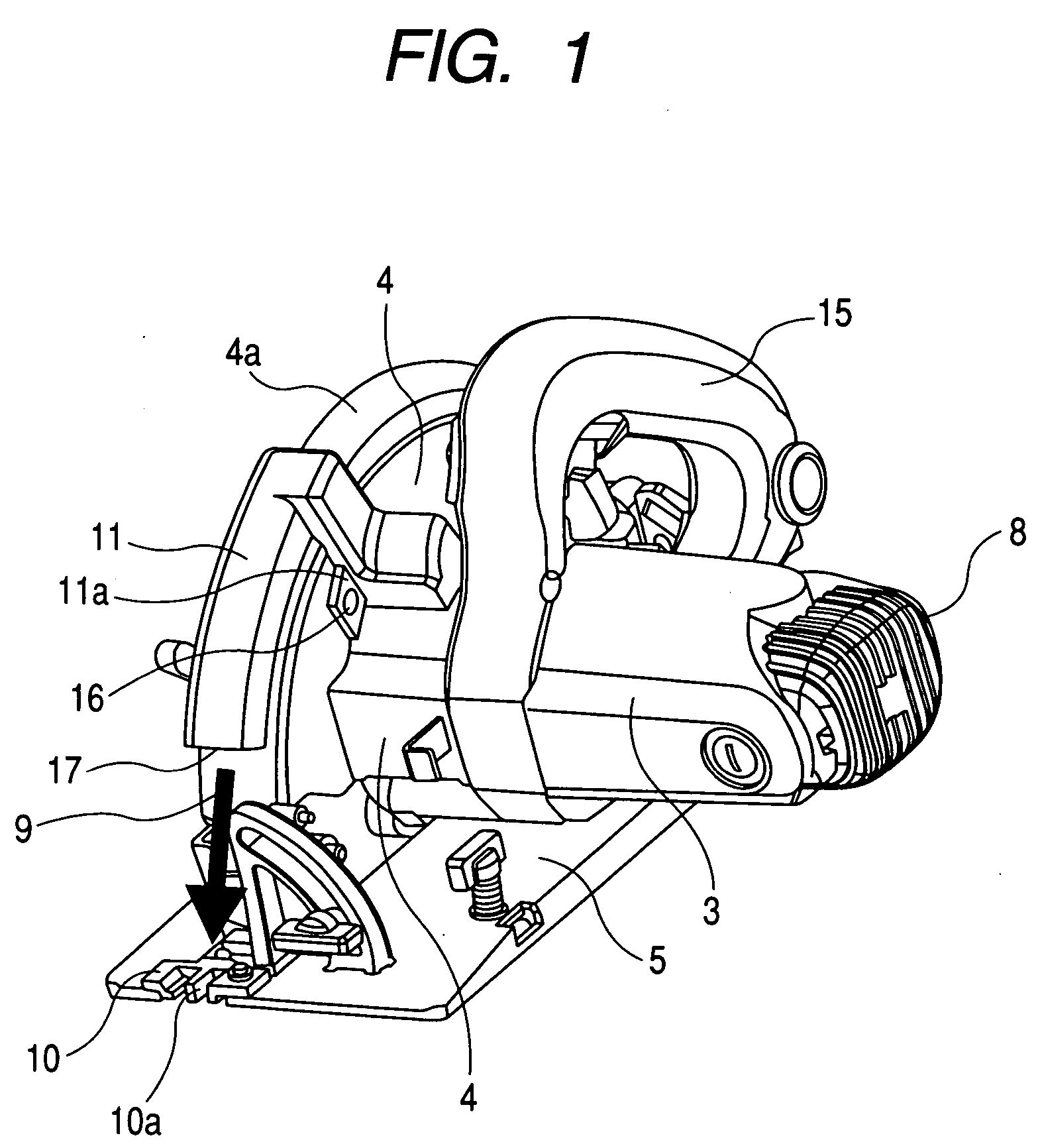
[0046]FIG. 1 is a perspective view of a portable circular saw according to a first embodiment of the invention, FIG. 2 is a perspective view to show a state in which a cover member of the portable circular saw is removed, FIG. 3 is a top perspective view of the cover member, FIG. 4 is a bottom perspective view of the cover member, FIG. 5 is a broken side view of the portable circular saw, FIG. 6 is a front perspective view of the cover member of the portable circular saw with parts partially broken away, and FIG. 7 is a bottom perspective view of the portable circular saw.

[0047] The portable circular saw according to the embodiment includes a saw blade 1, an electric motor 2 for rotating the saw blade 1, a motor housing 3 for housing the electric motor 2, a handle 15 projecting from the motor housing 3, a saw cover 4 for holding the saw blade 1 for rotation, and a base 5 placed below the motor housing 3 and the saw cover 4 and having an opening 5a for allowing the saw blade 1 to pr...

second embodiment

[0071] A second embodiment of the invention will be discussed with FIGS. 8 to 10.

[0072]FIG. 8 is a side view of a cover member of a portable circular saw with parts partially broken away according to the second embodiment of the invention, FIG. 9 is a broken side view of the portable circular saw, and FIG. 10 is a bottom view of the portable circular saw. Parts identical with those previously described with reference to FIGS. 1 to 7 are denoted by the same reference numerals in FIGS. 8 to 10 and will not be discussed again.

[0073] The portable circular saw according to the embodiment is characterized in that a laser oscillator 18 for emitting laser light L for guiding cutting toward the front side of a cut material in the cutting direction thereof is placed in a discharge passage 14 in a cover member 11, as shown in FIGS. 8 and 10, and other components are the same as those of the portable circular saw according to the first embodiment.

[0074] Since the laser light L emitted from t...

third embodiment

[0079] Next a third embodiment of the invention will be discussed with FIG. 11. FIG. 11 is a sectional side view of a jig saw according to the third embodiment of the invention.

[0080] The embodiment is provided by applying the invention to a jig saw. To begin with, the basic configuration and function of the jig saw will be discussed below:

[0081] An electric motor 32 as a drive source is housed as transversely mounted in a housing 31 of a jig saw shown in the figure, a pinion 34 is placed at one end of an output shaft (motor shaft) 33 of the electric motor 32 in one piece, and a fan 35 is attached onto the output shaft inside the pinion 34.

[0082] A shaft 36 is placed above and in parallel with the output shaft 33 of the electric motor 32 in the housing 31 and a gear 37 is supported on the shaft 36 for rotation and meshes with the pinion 34 formed at the end of the output shaft 33. A pin 38 eccentric with respect to the shaft 36 is attached to the gear 37 and engages a sleeve guid...


PUM

PropertyMeasurementUnit
Lengthaaaaaaaaaa
Lightaaaaaaaaaa

Abstract

A portable electric cutting apparatus includes a housing for housing an electric motor for rotating a saw blade a fan provided in the housing and driven by the electric motor, a saw cover attached to the housing and having a saw blade housing part having a shape to cover an upper half of the outer periphery of the saw blade for housing a part of the saw blade, a base formed with an opening for allowing the saw blade to project downward from a bottom face which is slidable on a cut material. A discharge passage for discharging a fan wind produced by driving the fan is formed along an outer periphery of the saw cover. The fan wind is discharged through the discharge passage toward a front side of the base in the cutting direction.

Description

BACKGROUND OF THE INVENTION [0001] 1. Field of the Invention [0002] The invention relates to a portable electric cutting apparatus of a portable circular saw, a portable jig saw, etc., having a fan for cooling an electric motor. [0003] 2. Description of the Related Art [0004]FIGS. 12 and 13 show the configuration of a portable circular saw as an example of a portable electric cutting apparatus in a related art. [0005]FIG. 12 is a broken plan view of a portable circular saw in a related art and FIG. 13 is a bottom perspective view of the portable circular saw on the rear thereof. The portable circular saw shown in the figures includes a saw blade 1, an electric motor 2 for rotating the saw blade 1, a motor housing 3 for housing the electric motor 2, a saw cover 4 for holding the saw blade 1 for rotation, and a base 5 placed below the motor housing 3 and the saw cover 4 and having an opening 5a for allowing the saw blade 1 to project from the lower face. The saw cover 4 is attached to...

Claims


Application Information

Patent Timeline
IPC IPC(8): B23D49/16B23D47/00B23D59/00B23Q17/24B27B9/00
CPCB23Q17/2404B23D59/006
Inventor TANIMOTO, HIDEYUKIIMAI, TERUONIWA, KENJIKONNAI, TAKUYA
Owner HITACHI KOKI CO LTD
Why Eureka
Try Eureka