Pressure sensors having transducers positioned to provide for low drift

a technology of transducer and pressure sensor, which is applied in the field of pressure sensor transducer positioning to provide low drift, and can solve the problems of currently available pressure sensor drift, adverse effect of chip, and increased resistan

Active Publication Date: 2005-07-28
PROTEUS DIGITAL HEALTH INC
View PDF17 Cites 55 Cited by
  • Summary
  • Abstract
  • Description
  • Claims
  • Application Information

AI Technical Summary

Benefits of technology

[0012] Implantable pressure sensors and methods for making and using the same are provided. A feature of embodiments of the subject pressure sensors is that they are low-drift sensors. The subject sensors find use in a variety of applications.

Problems solved by technology

The effectiveness of the chip is adversely effected, however, by the fact that one resistance also increases and the other decreases when force is applied to the chip as a whole, such as bending, stretching and twisting forces.
Over extended periods of use, currently available pressure sensors experience drift.
The variable quality of baseline sensor data drift in the sense of output interferes with obtaining data which accurately reflects changes in physiologic parameters.
Drift obscures accurate data both by producing false positive and false negative readings.
By example, false negative results can occur when drift of base-line data readings distorts or fully obscures physiologic parameter changes in signal which would otherwise be indicative of a disease state.
Conversely, when sensor drift is in a positive range it can be mistaken for a change in biological parameters, running the risk of a false indication of a disease state.
Unfortunately, drift is typically unpredictable, and so can not be simply factored out of calculations in order to compensate for these data distortion.
The drift characteristic of many pressure sensors can be problematic with implanted sensors, where recalibration opportunities are limited or impractical.
Because of the limited ability to recalibrate implanted sensors, the failure of currently available pressures sensors to remain stable (i.e., free of drift) in base-line data output has made them unsuitable for long term implantable use.

Method used


Image

  • Pressure sensors having transducers positioned to provide for low drift
  • Pressure sensors having transducers positioned to provide for low drift
  • Pressure sensors having transducers positioned to provide for low drift

Examples


Embodiment Construction

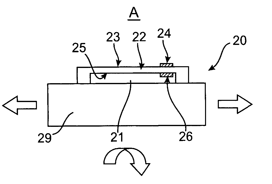
[0069] Low-drift implantable pressure sensors and systems including the same, as well as methods of making and using the same, are provided. The subject sensors are characterized by having at least a substrate, a compliant member mounted on the substrate in a manner such that the compliant has first and second exposed surfaces, and at least one strain transducer associated with a surface of the compliant member. A feature of the subject devices is that they exhibit low-drift. The subject devices and methods find use in a variety of different applications.

[0070] Before the present invention is further described, it is to be understood that this invention is not limited to particular embodiments described, as such may, of course, vary. It is also to be understood that the terminology used herein is for the purpose of describing particular embodiments only, and is not intended to be limiting, since the scope of the present invention will be limited only by the appended claims.

[0071] ...


PUM

PropertyMeasurementUnit
widthaaaaaaaaaa
widthaaaaaaaaaa
angleaaaaaaaaaa

Abstract

Implantable pressure sensors and methods for making and using the same are provided. A feature of embodiments of the subject pressure sensors is that they are low-drift sensors. The subject sensors find use in a variety of applications.

Description

CROSS-REFERENCES TO RELATED APPLICATIONS [0001] The present application claims priority to PCT / US ______ (Atty. Docket No. 021308-000220PC) filed Dec. 10, 2004, which in turn claims priority to U.S. Provisional Patent Application Ser. No. 60 / 529,325 filed Dec. 11, 2003; U.S. Provisional Patent Application Ser. No. 60 / 615,117 filed Sep. 30, 2004; U.S. Provisional Patent Application Ser. No. 60 / 616,706 filed Oct. 6, 2004; and U.S. Provisional Patent Application Ser. No. 60 / 624,427 filed Nov. 1, 2004; the disclosures of which are herein incorporated by reference.BACKGROUND OF THE INVENTION [0002] Monitoring pressures and pressure changes in a human body is often an important component of a medical or surgical diagnosis or therapy. For example, pressure changes in various body chambers, such as blood pressures in chambers of the heart, may be used for diagnosis and / or treatment of a number of conditions. One or more pressure sensors positioned in a heart chamber, for example, may allow ...

Claims


Application Information

Patent Timeline
Patent Type & Authority Applications(United States)
IPC IPC(8): A61BA61B5/0215A61N1/362A61N1/365G01L9/00G01L9/04G01L9/06H01L21/44H01L21/48
CPCA61B5/0215A61B5/412A61B2562/02A61N1/3627G01L9/065G01L9/0042G01L9/0055G01L9/045A61N1/36564
Inventor ZDEBLICK, MARKCOSTELLO, BENEDICT JAMES
Owner PROTEUS DIGITAL HEALTH INC
Why Eureka
Try Eureka