Linear movement/rotation mechanism equipped with a ball screw/ball spline mechanism

a technology of ball screw and ball spline, which is applied in the direction of mechanical equipment, gearing, hoisting equipment, etc., can solve the problems of low belt strength, low positioning accuracy of belt/pulley transmission mechanism, and low positioning accuracy of drive shaft, etc., to achieve accurate positioning of drive shaft

Inactive Publication Date: 2005-07-28
HARMONIC INC
View PDF4 Cites 8 Cited by
  • Summary
  • Abstract
  • Description
  • Claims
  • Application Information

AI Technical Summary

Benefits of technology

[0011] In view of the above problem, it is a main object of the present invention to provide a linear movement/rotation mechanism...

Problems solved by technology

Compared to other transmission mechanisms such as gear trains, positioning accuracy of the belt/pulley transmission mechanism is low, and...

Method used


Image

  • Linear movement/rotation mechanism equipped with a ball screw/ball spline mechanism
  • Linear movement/rotation mechanism equipped with a ball screw/ball spline mechanism
  • Linear movement/rotation mechanism equipped with a ball screw/ball spline mechanism

Examples


Embodiment Construction

[0040] Preferred embodiments of a linear movement / rotation mechanism equipped with a ball screw / ball spline mechanism according to the present invention will now be described with reference to the drawings.

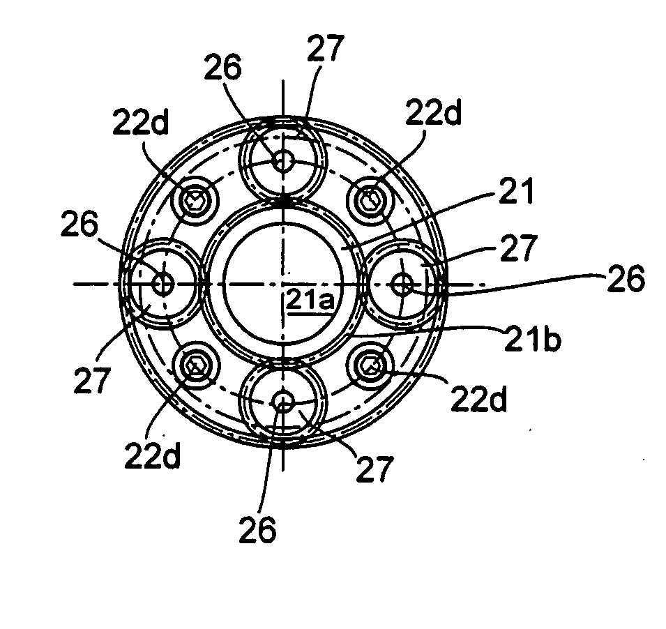
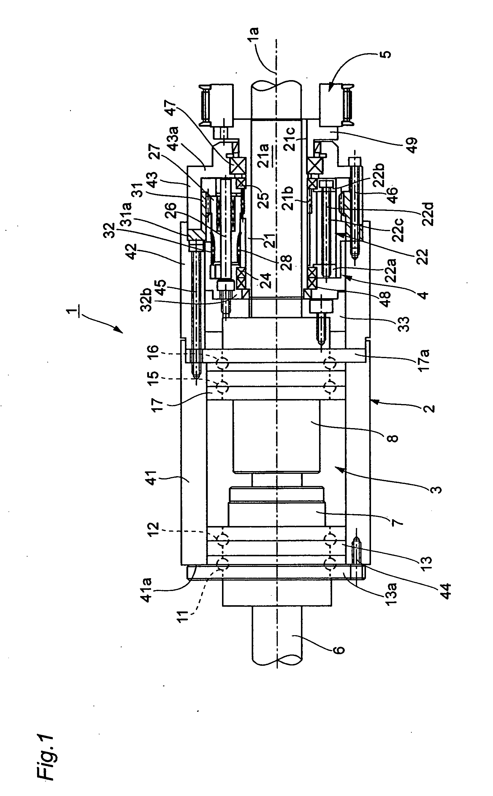
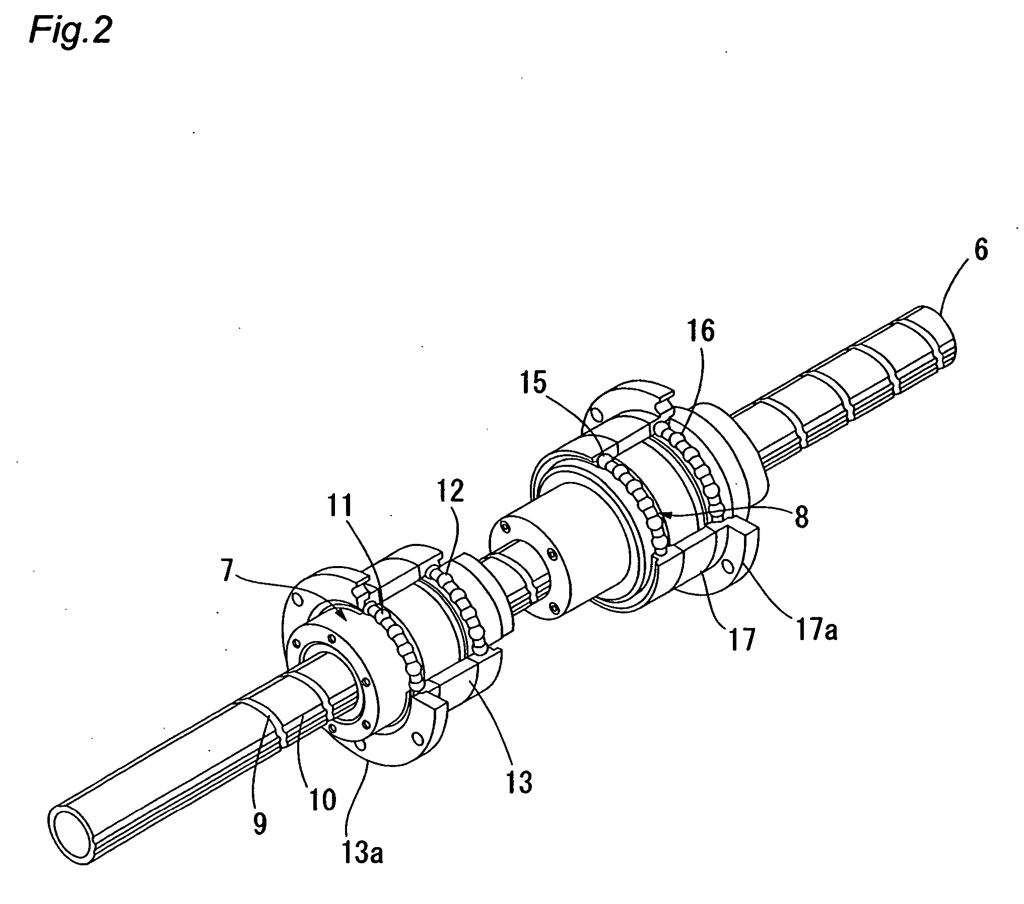
[0041]FIG. 1 is a longitudinal cross-sectional view of a linear movement / rotation mechanism, FIG. 2 is an explanatory view of a ball screw / ball spline mechanism of the linear movement / rotation mechanism, and FIGS. 3A and 3B are respectively a longitudinal cross-sectional view of a hollow planetary reduction gear and a schematic diagram showing arrangement of planetary gears. The linear movement / rotation mechanism 1 includes a tube-like housing 2, a ball screw / ball spline mechanism 3 and a hollow planetary reduction gear 4 that are coaxially connected inside the tube-like housing 2, a driven pulley 5 as a rotation input member for inputting a rotational force into the hollow planetary reduction gear 4, and a drive shaft 6 that extends so as to pass through the respective component...


PUM

PropertyMeasurementUnit
Forceaaaaaaaaaa

Abstract

In a linear movement/rotation mechanism, inside a tube-like housing, a ball screw/ball spline mechanism and a hollow planetary reduction gear are coaxially disposed, a drive shaft extends therethrough, and a ball screw nut, a ball spline nut, a hollow planetary reduction gear, and a driven pulley are disposed in that order along a center axis of the drive shaft. A rotational force inputted to the driven pulley is inputted to a hollow rotational shaft of the hollow planetary reduction gear, and a reduced rotation output is outputted from a rear stage internal gear. The reduced rotation output is transmitted to the ball spline nut that is connected and fixed to the rear stage internal gear. When the rotation of the ball screw nut is restricted, a feeding operation of the drive shaft is realized.

Description

BACKGROUND OF THE INVENTION [0001] 1. Field of the Invention [0002] The present invention relates to a linear movement / rotation mechanism that linearly and / or rotationally moves a drive shaft using a ball screw / ball spline mechanism. [0003] 2. Related Art [0004] A mechanism that uses a ball screw and a ball spline is known as one example of a mechanism for linearly or rotationally driving a drive shaft. A ball screw / ball spline mechanism constructed so that a ball screw thread and a ball spline groove are formed in an outer circumferential surface of a drive shaft so as to intersect one another and a ball screw nut that engages the ball screw thread and a ball spline nut that engages the ball spline groove are attached to the drive shaft is also known (see Patent Documents 1, 2). [0005]FIG. 6 shows a typical linear movement / rotation mechanism that is equipped with the ball screw / ball spline mechanism of the above construction. A linear movement / rotation mechanism 100 includes a redu...

Claims


Application Information

Patent Timeline
IPC IPC(8): B29B13/00F16H25/20F16H25/22F16H37/02
CPCF16H25/2018Y10T74/19795F16H2025/2087F16H25/2204E06B3/9648E06B3/9682
Inventor AIDA, YOSHINORISHIRASAWA, NAOMIMISAWA, TOSHIAKI
Owner HARMONIC INC
Why Eureka
Try Eureka