Method and program solving LCPs for rigid body dynamics

a rigid body and program technology, applied in the field of method and program solving lcps for rigid body dynamics, can solve the problems of difficult practical development of physics-based animations, including rigid body simulations, and the loss of illusion of object rigidity, and achieve the effect of solving very small cases with algebraic solutions and reducing the difficulty of implementation

Active Publication Date: 2005-07-28
NVIDIA CORP
View PDF1 Cites 25 Cited by
  • Summary
  • Abstract
  • Description
  • Claims
  • Application Information

AI Technical Summary

Benefits of technology

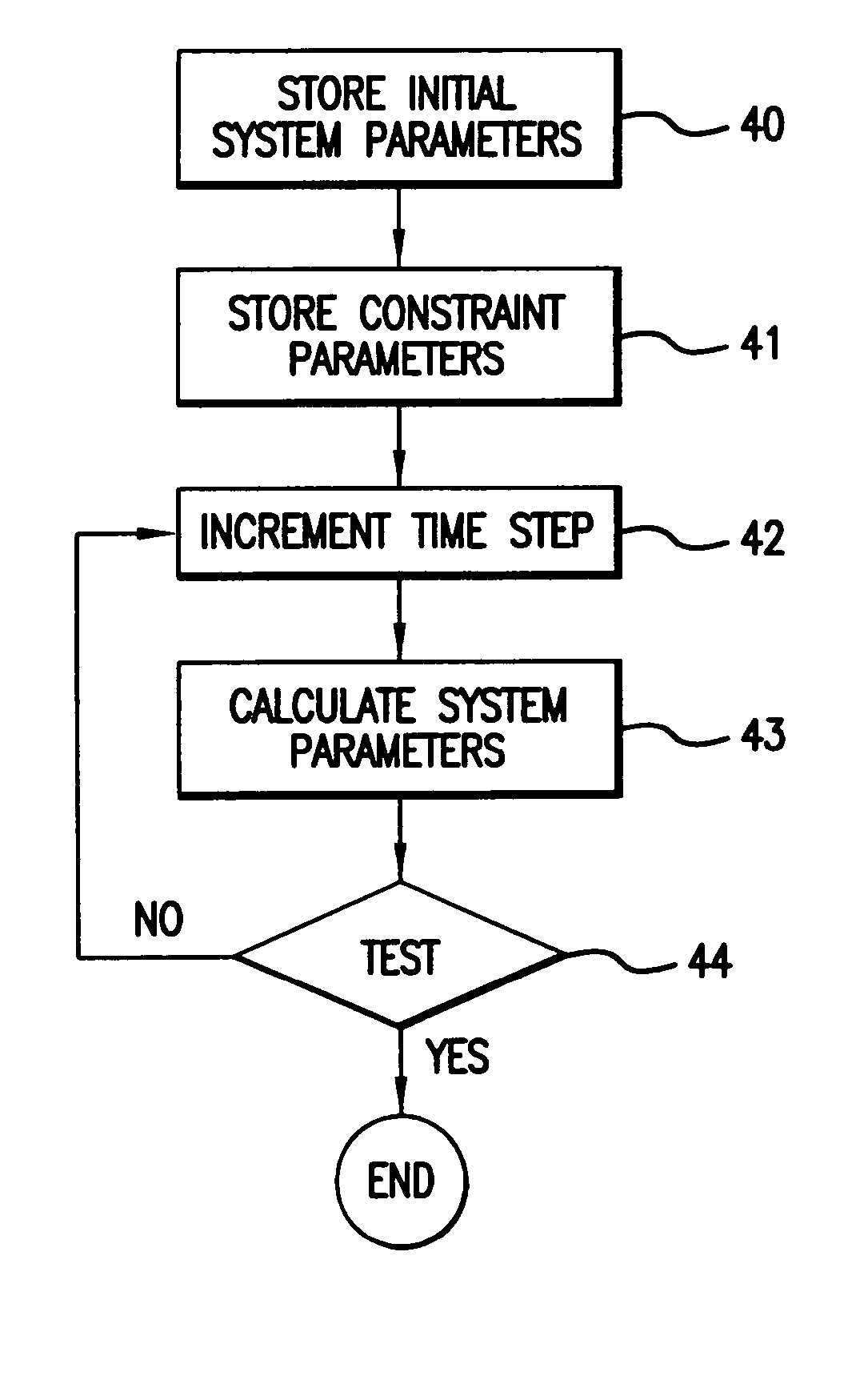
[0038] In yet another related aspect, the present invention provides a computational method for resolving a Linear Complementarity Problem (LCP) derived from a data set. The data set is defined in relation to a plurality of rigid bodies and one or more constraints defining limitations upon the motion of the rigid bodies. The method applies a projected iterative descent method to data forms derived from the data set during a fixed maximum time period. Of note, the fixed maximum time period allows real-time animation of the dynamic interaction of the rigid bodies on a display system.

Problems solved by technology

If a simulator were to allow large penetrations of objects, then the illusion of object rigidity would be lost.
The practical development of physics-based animations, including rigid body simulations, has proved quite difficult.
However, the set of cases which have algebraic solutions is very small and a rigid body simulator must be able to handle any configuration of contacting rigid bodies.
Given that frames of animation are only required at discrete time intervals, this is an acceptable limitation.
Selecting a discrete model that approximates a sufficiently large class of continuous problems and is solvable in real time by a computer is difficult.
A poor choice of discrete model can result in behavior that diverges unacceptably from the original continuous problem.
For example with a bad model, objects might jump around for no reason, penetrate unacceptably, fall through a floor, or fly off into infinity.
This result arises because unlike simulations used in science and engineering, computer game simulations need not be predictive.
However, although this relaxed requirement makes it easier to meet the real-time constraint, it unfortunately doesn't make the mathematics any easier.
Solving the necessary equations of motion to realistically animate objects has proved to be a difficult problem since accuracy (i.e., realism) and computational speed are always at odds.
As well as being quite boring for the user, the animation could not take into account the context of the action.
For example, if the user pressed the punch key next to a wall, there would often be nothing to stop the player's arm going through the wall.
If the user had previously parked a car behind the pile of boxes, the boxes would typically fall through the car.
These problems were overcome to a certain extent by limiting the actions of the user, for example by not giving the user a car to drive, not allowing the user to walk within arm's length of a wall and not allowing fights next to cliffs.
These restrictions were often frustrating to the user.
Thus, as game complexity increases the cost associated with the development of multiple animations becomes prohibitive.
As the game design progresses, some additional constraints are added however, as most fun games have rules.
Unfortunately, contemporary physics engines have significant limitations as to the number of objects in an animated scene, and more particularly, the number of active (i.e., moving or interacting) objects.
Increasing complexity of terrain geometry greatly increases the difficulty of simulating object interactions with the terrain.
The complexity of collision detection and resolution also increases with the complexity of an object's surface geometry (i.e., its surface detail).
However, among the factors challenging the realistic, real-time animation of objects in a physics-based application, the definition and incorporation of constraints upon the animated rigid body objects has proved most difficult.
Indeed, it the existence of numerous constraints that makes the underlying mathematical (numerical analysis) problem much more difficult to resolve, as compared with a simple application of Newton's laws of motion.
In such an approach, the Lagrange multipliers result in a large number of variables being used—nearly doubling the variables otherwise required to describe the animation.
Early LCP methods proved unreliable because there was no guarantee of the existence of a solution in the presence of contact with Coulomb friction.
However, both approaches are impractically slow for use within real-time animations and overly prone to large computational errors.
Yet, all of the foregoing approaches to the resolution of LCPs arising from consideration of systems containing constrained, rigid bodies remain unsuited for real-time applications, unless such systems are greatly restricted in size and / or complexity.
The conventional approaches are simply too slow.
This slowness generally results from the use inefficient computational methods and inappropriate data forms.

Method used


Image

  • Method and program solving LCPs for rigid body dynamics
  • Method and program solving LCPs for rigid body dynamics
  • Method and program solving LCPs for rigid body dynamics

Examples


example 1

PSEUDO CODE EXAMPLE 1

[0080]

f, x := 0, 0while x ≠ numIterationsi:=0while i ≠ mfi := max(0, fi − aii−1(bi + (Af)i))(9)i := i + 1endwhilex := x + 1endwhile

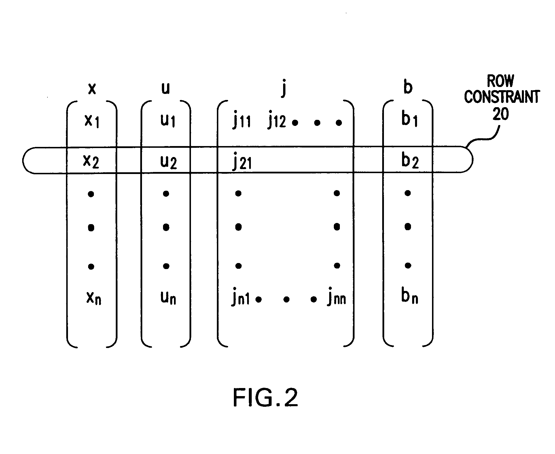
[0081] As can clearly be seen in equation (9) above, the projected iterative descent method is most computationally intense (or “dominated” by) the repeated multiplication of system matrix A by f. Thus, in so far as the this computational step can be simplified or reduced in iteration, the speed with which the LCP is resolved will be increased. Within the context of the present invention, the particular structure of system matrix A may be exploited by introducing an auxiliary variable which will significantly reduce the cost of the dominate computation noted above.

[0082] Although system matrix A is actually the mathematical product of three separate matrices, it is convenient to express A as the product of Jacobian, J, and the transpose of a “Jacobian / Mass” matrix JM, where JM is defined as the product of J and the mass-inertia matr...

code example 2

PSEUDO-CODE EXAMPLE 2

[0085]

f, v, x := 0, 0, 0while w ≠ numIterationsi := 0while i ≠ mfi := max(0, fi − aii−1(bi + (Jv)i))(12)v := (JM)T f(13)i := i + 1endwhilex := x + 1endwhile

[0086] The term (bi+(Jv)i) in the computational step above also has a physical interpretation, i.e. constraint space velocity for a current constraint row i, or more correctly the rate of change of the constraint violation for row constraint i. Considering that only one element of f changes per iteration, auxiliary variable v can be updated in an incremental way. This recognition allows the working Pseudo-Code example to be further optimized as shown below.

code example 3

PSEUDO-CODE EXAMPLE 3

[0087]

f, v, x := 0, 0, 0while x ≠ numIterationsi := 0while i ≠ mnewf := max(0, fi − aii−1(bi + (Jv)i))(14)v := v + (JM)iT(newf − fi)(15)fi := newfi := i + 1endwhilex := x + 1endwhile

[0088] As can be seen from (15) above, “newf” is an intermediate value that will be assigned back into the current candidate solution “fi”. The term “newf-fi” is thus used to incrementally update auxiliary variable v. Of note, equation (13) in Pseudo-Code example 2 requires the multiplication of a large matrix JM (size=6 n by m) with a large vector, candidate solution f (size=m). However, use of auxiliary variable v allows equation (15) in Pseudo-Code example 3 to replace this complex multiplication step with a small vector scaling and addition. Replacement of the complex, large-matrix by large vector multiplication step with a simple, scaled vector addition step, (newf-fi), greatly reduces the number of floating point operations required to compute each iteration.

[0089] The project...


PUM


Abstract

A projected iterative descent method is used to resolve LCPs related to rigid body dynamics, such that animation of the rigid body dynamics on a display system occur in real-time.

Description

[0001] This application claims the benefit of U.S. Provisional Patent Application No. 60 / 537,954 filed Jan. 22, 2004.BACKGROUND OF THE INVENTION [0002] The present invention relates to a method and program for realistically animating the motion and interaction of rigid bodies in a display system. More particularly, the present invention relates to a method and program for solving a class of Linear Complementary Problems (LCPs) that arise during operation of a rigid body dynamics engine within the display system. The present invention finds application within conventional display systems, as well as within recently proposed display systems incorporating a hardware-based, physics processing unit. [0003] Physics-based “animations” and “simulations” (hereafter these terms are used interchangeably regardless of application, specific method of display, or means of communicating related physics-based data) have been extensively investigated during the past three decades. Such animations ar...

Claims


Application Information

Patent Timeline
Patent Type & Authority Applications(United States)
IPC IPC(8): G06T13/00
CPCA63F2300/646G06F17/11G06F17/5018G06T13/20G06F2217/16G06T19/00G06T2200/28G06F2217/06G06F30/23G06F2111/04G06F2111/10
Inventor TONGE, RICHARDZHANG, LIHUASEQUEIRA, DILIP
Owner NVIDIA CORP
Why Eureka
Try Eureka