Optical pickup device with a plurality of laser couplers

Inactive Publication Date: 2005-07-28
SONY CORP
View PDF2 Cites 5 Cited by
  • Summary
  • Abstract
  • Description
  • Claims
  • Application Information

AI Technical Summary

Benefits of technology

[0006] It is, therefore, an object of the invention to provide an optical pickup device that can be used for both reading from and writing to different kinds of optical discs having different read / write formats, and yet has a small-scaled, easily assembled structure.
[0007] Another object of the invention is to provide a composite optical device that can be used for both reading from and writing to different kinds of optical discs having different read / write formats when used in an optical pickup device, and contributes to miniaturization and easier assembly of the optical pickup device.
[0014] The optical pickup device having the above construction according to the invention can be used for both reading of and writing to different kinds of optical discs having different formats by designing its composite optical devices to have specifications in accordance with the different kinds of optical discs. Since the composite optical devices can be miniaturized, the optical pickup device also can be small-scaled. Moreover, since light emitting elements, photodetectors and transparent optical elements in the composite optical devices are previously adjusted in optical axis, etc., the optical pickup device can be assembled easily.
[0015] The composite optical device having the above construction according to the invention can be used for both writing to and reading of different kinds of optical discs having different formats by designing individual light emitting elements to have specifications in accordance with the different kinds of optical discs. Since the composite optical device can be miniaturized, a miniaturized optical pickup device can be made by using the optical pickup device. Moreover, since optical axes, etc. of light emitting elements, photodetectors and transparent optical elements in the composite optical devices can be adjusted easily like those of a conventional composite optical device having a single light emitting element, they can be assembled easily.

Problems solved by technology

However, the use of different optical pickup devices for respective optical discs of different formats invites an increase in the dimensions and cost of the optical disc system.
Especially when a packaged writing semiconductor laser and a packaged reading semiconductor laser are used to make up an optical pickup device, the optical pickup device itself, and an optical disc system using it, become more bulky.
At the same time, these semiconductor lasers and photodetector elements are difficult to assemble because adjustment of their optical axes is more difficult than conventional devices.

Method used


Image

  • Optical pickup device with a plurality of laser couplers
  • Optical pickup device with a plurality of laser couplers
  • Optical pickup device with a plurality of laser couplers

Examples


first embodiment

[0039] Based on the description made above, the invention is explained below. In this embodiment, two laser couplers explained above are used to form an optical pickup device.

[0040]FIG. 6 shows the optical pickup device according to the first embodiment of the invention.

[0041] As shown in FIG. 6, the optical pickup device according to the first embodiment is made up of two laser couplers LC1 and LC2, half mirror HM and objective lens OL. The laser coupler LC1 and LC2 may have the construction shown in FIGS. 1 and 2, for example. In this case, the laser coupler LC1 is disposed to share a common optical axis with the half mirror HM and the objective lens OL. The laser coupler LC2 is disposed to substantially coincide its incident or exit optical axis with the incident or exit optical axis of the laser coupler LC1 on the half mirror HM. The half mirror HM preferably has a polarizing function to polarize laser beams from the laser couplers LC1 and LC2 into different polarized beams to ...

second embodiment

[0045]FIG. 7 shows a laser coupler taken as the invention, which is used in an optical pickup device.

[0046] As shown in FIG. 7, the laser coupler according to the second embodiment includes two laser couplers LC1 and LC2 having the same construction shown in FIGS. 1 and 2 and supported in close locations on a common photodiode IC 1 to orient their optical axes in parallel with each other. Like those in the first embodiment, the laser couplers LC1 and LC2 are individually designed in optimum specifications each for record and reproduce of one kind of optical discs in a particular format.

[0047] The distance between the LOP chip of the laser coupler LC1 and the LOP chip of the laser coupler LC2 is typically around 500 um, and 30 to 400 um in minimum, although depending on the mounting accuracy of these LOP chips.

[0048] When an optical pickup device is made by using the laser coupler according to the second embodiment, the objective lens may be an integral body with or a separate body...

third embodiment

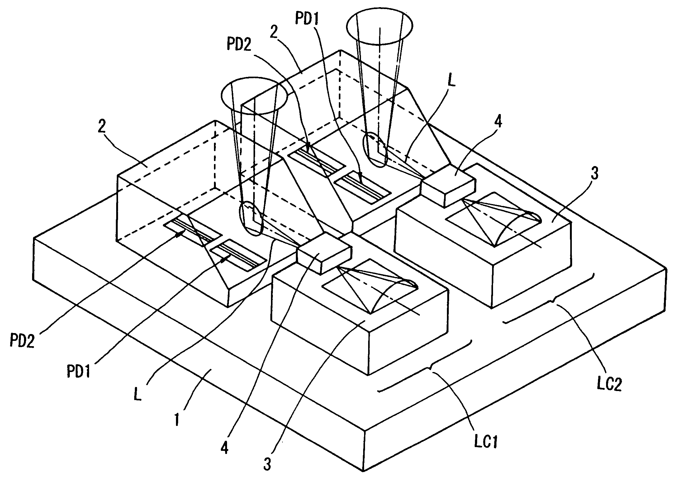
[0052]FIG. 8 shows a laser coupler taken as the invention, which is used in an optical pickup device.

[0053] As shown in FIG. 8, in the laser coupler according to the third embodiment, a single common microprism is used for both laser couplers LC1 and LC2. A single sloped surface 2a is used by both laser couplers LC1 and LC2. In the other aspects, the third embodiment is the same as the laser coupler of the second embodiment, and its explanation is omitted here.

[0054] Here again, when an optical pickup device is made by using the laser coupler according to the third embodiment, the objective lens may be an integral body with or a separate body from the laser coupler, and the laser couplers LC1 and LC2 can commonly use a single objective lens.

[0055] Also the third embodiment has the same advantages as those of the second embodiment.


PUM


Abstract

An optical pickup device with the capability to read data from and write data to different kinds of optical discs in different formats and a composite optical device used in the optical pickup device. An optical pickup device is made by combining two laser couplers LC1 and LC2 that are designed for optimum read / write specifications for optical discs which are different in format from each other. In one embodiment, two laser couplers LC1 and LC2 are incorporated on a common photodiode IC to form a single laser coupler, and the laser coupler is used in an optical pickup device.

Description

BACKGROUND OF THE INVENTION [0001] The invention relates to optical pickup devices and composite optical devices especially suitable for use in an optical disc system. [0002] Along with the recent diversification of optical disc systems, there has been an increase in incompatible optical discs using what are referred to herein as different read / write formats (or simply formats) (for example, CD, CD-R, MD, MO, Phase Change Disc DVD, and so on). These read / write formats can very, e.g., by using laser light from a semiconductor laser for emitting light in the band of 780 nm, laser light from an emitting semiconductor laser for emitting red light in the band of 635 nm (or 650 nm), laser light from a semiconductor laser for emitting blue light, and so forth. The optical pickup devices used to read from and write to these different optical recording media then have what are referred to herein as different read / write specifications. [0003] In order to use a common optical disc system to re...

Claims


Application Information

Patent Timeline
IPC IPC(8): G11B7/00G11B7/12G11B7/125G11B7/13G11B7/135G11B11/105
CPCG11B7/1205G11B7/127G11B7/131G11B2007/0006G11B7/1359G11B11/10543G11B7/1356G11B7/123
Inventor TANIGUCHI, TADASHIKOJIMA, CHIAKI
Owner SONY CORP
Why Eureka
Try Eureka