Electronic clinical thermometer

a thermometer and electronic technology, applied in the field of electronic thermometers, can solve the problems of long computer time wasted, unstable solution, and inability to fully take into account individual variations of patients or environmental changes, and achieve the effect of convenient keeping the thermometer in position

Inactive Publication Date: 2005-07-28
ORMON CORP
View PDF22 Cites 8 Cited by
  • Summary
  • Abstract
  • Description
  • Claims
  • Application Information

AI Technical Summary

Benefits of technology

[0007] It is therefore an object of this invention to provide an electronic clinical thermometer capable of accurately and quickly estimate the internal body temperature of a live body by measuring real-time external temperature values directly and calculating the temperature at the desired internal body position by solving an equation of thermal conduction and using the results of such measurements.
[0008] In view of the above and other objects of this invention, the temperature on an external surface of a live body is measured directly on real time according to this invention and the body temperature at a normally inaccessible internal position of the body is estimated on the basis of values thus obtained. For this purpose, an equation of thermal conduction is used in reverse, Such an equation is solved as a lower-order equation such as a first-order differential equation including measurable physical quantities such as the body surface temperature and the thermal flux as variables. The desired internal temperature is then estimated by directly measuring these physical quantities. If as many different measured quantities are obtained as there are variables, the internal temperature can be obtained accurately and quickly by solving simultaneous first-order equations.

Problems solved by technology

This method cannot fully take into account individual variations among patients or environmental changes.
As for the method according to International Patent Publication WO-9850766, the solution is unstable because the equation to be solved is non-linear and an accurate solution cannot be obtained without the help of a high-power computer, and a long computer time will be wasted.

Method used


Image

  • Electronic clinical thermometer
  • Electronic clinical thermometer
  • Electronic clinical thermometer

Examples


first embodiment

[0059]FIGS. 8A and 8B show another electronic thermometer 11 which may be considered a variation of the invention, structured in the shape of a flat rectangular parallelopiped with one end in a semi-circular form from which a probe 20 in the form of a circular column protrudes. A display device 4 comprising an LCD and a power switch 5 are disposed on the opposite surface.

second embodiment

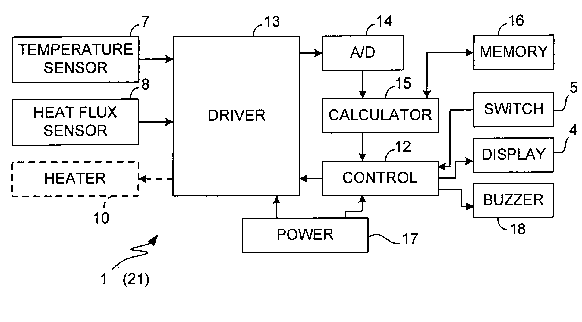
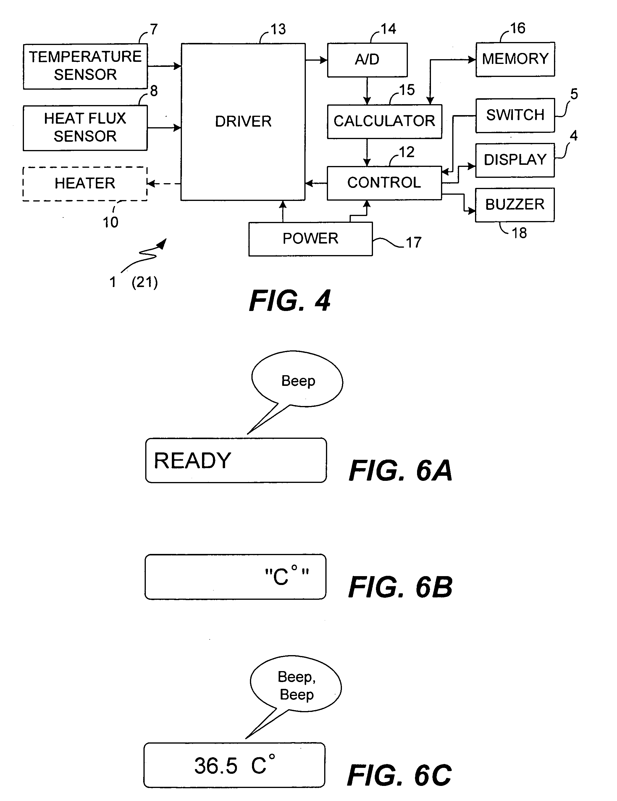
[0060] As shown in FIG. 9A, the probe 20 has its upper and side surfaces covered with a thin cover layer 26, say, of SUS. A temperature sensor 7 and a heat flux sensor 8 are disposed on the lower surface of the top part 26a of the cover layer 26. A circular disk-shaped insulating member 9 is disposed below the top part 26a of the cover layer 26, sandwiching the temperature sensor 7 and the heat flux sensor 8 with the top part 26a of the cover layer 26. A heater 10 may be disposed (according to the invention) on the lower surface of the insulating member 9. As shown in FIG. 9B, the temperature sensor 7 and the heat flux sensor 8 are positioned on the top part 26a of the cover layer 26 proximally to each other.

[0061] The thermometer 11 thus structured is particularly advantageous for use by an infant who may find it difficult to hold the probe steadily under an arm or under the tongue.

[0062] Next, the process of taking temperature measurement according to the second embodiment of the...

third embodiment

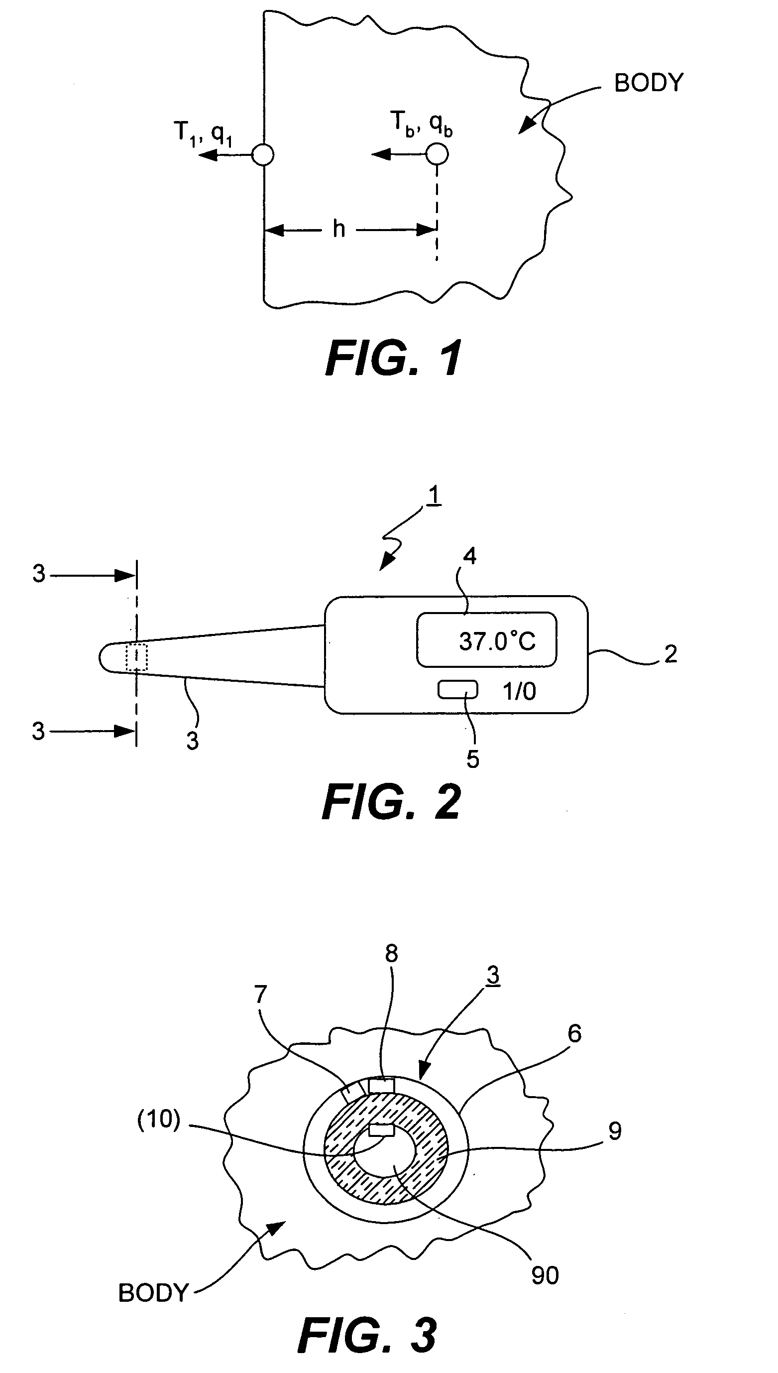
[0066]FIG. 11 is referenced next to explain the principle of temperature measurement by a thermometer 31 according to the invention shown in FIGS. 12 and 13.

[0067] The third embodiment is characterized as using two insulating members with different thermal conductivity values, or to estimate the temperature Tb at an internal target body position by measuring temperatures T1 and T2 at different surface positions at a distance h from the target position respectively through an insulating layer with thermal conductivity λ1 and λ2. Thus, by solving the differential equation of thermal conduction by keeping the second-order terms. as done above, we obtain:

Tb=Ts1+(h / λb)q1+(h2 / 2α1)(dT1 / dt)

Tb=Ts2+(h / λb)q2+(h2 / 2α2)(dT2 / dt)

where λb is the thermal conductivity of the body, Ts1 and Ts2 are respectively the temperature at the contact surface between the body and the first and second insulating member, q1 and q2 are respectively the heat flux through the first and second insulating member, and α...


PUM

PropertyMeasurementUnit
temperatureaaaaaaaaaa

Abstract

An electronic clinical thermometer has a probe including a temperature sensor and a heat flux sensor which are controlled to make measurements at specified time intervals. The measured values are used in solving the equation of heat conduction to estimate the temperature of an internal body position. A heater may be included to preheat a body part in order to reduce the time required for measurement. The probe may use two temperature sensors to measure temperatures at two body surface positions through insulating members which are different in thermal conductivity.

Description

BACKGROUND OF THE INVENTION [0001] This invention relates to an electronic thermometer for estimating the temperature at an inner position of a live body based on temperature data taken on the body surface. More particularly, the invention relates to such an electronic thermometer using an equation of thermal conduction for making such an estimate. [0002] When a conventional clinical thermometer such as a mercury thermometer is used to measure the temperature of a body by having it held under an arm or the tongue, the thermometer must be kept in that position until a thermal equilibrium is reached between the internal body position of interest and the surface temperature. [0003] Japanese Patent Publication Tokko Hei 7-119656 B2 disclosed a method of using an equation for estimating the change in temperature while reaching an equilibrium and regarding such an equilibrium temperature as the body temperature. [0004] It is desirable, however, to measure the internal body temperature of ...

Claims


Application Information

Patent Timeline
Patent Type & Authority Applications(United States)
IPC IPC(8): G01K1/16G01K7/42
CPCG01K7/42G01K1/16
Inventor TOKITA, MUNEONAKAJIMA, SATOSHIMAKITA, SHIGERU
Owner ORMON CORP
Why Eureka
Try Eureka