
Conductivity measurement cell

a measurement cell and conductivity technology, applied in the direction of logic circuits, instruments, and analysis by subjecting materials to chemical reactions, can solve the problems of preventing accurate diagnosis, cumbersome optical measurement apparatus, and substantial affecting the measured analyte concentration, so as to achieve rapid and accurate measurement results and reduce the number of components required

Active Publication Date: 2017-06-27
SPD SWISS PRECISION DIAGNOSTICS
View PDF30 Cites 0 Cited by
  • Summary
  • Abstract
  • Description
  • Claims
  • Application Information

AI Technical Summary

Benefits of technology

The invention provides a way to quickly and accurately measure temperature by measuring the conductance of a reference and a sample. This is done using a membrane and shared electrodes, which allows the temperature to be matched quickly. The use of individual meters and test strips allows for individual calibration and compensates for any variations in manufacture between the strips and meters. Overall, the invention simplifies the temperature measurement process and improves accuracy.

Problems solved by technology

However, depending on the level of hydration of the patient, urine may be relatively dilute or concentrated and this variability in urine dilution can substantially affect the measured analyte concentration, preventing accurate diagnosis.
However, the apparatus required for measuring creatinine concentration by optical means is cumbersome and expensive.
The analyser relies upon a temperature controller having a heater and thermistor, is bulky, power hungry and unsuitable for adapting to a hand held disposable assay device.
However, electrical conductivity of a sample is known to vary with sample temperature, therefore a temperature dependent error exists in the corrected analyte concentration result.
The disclosure is unsuitable for use in a convenient point of care device, such as a disposable assay device, since its features render it relatively expensive and unsuitable for interfacing to a microprocessor.
The disclosed device is also susceptible to errors in temperature compensation if the blood sample and the reference are not maintained at the same temperature as each other.
In addition, the performance of the apparatus changes over time requiring repeated calibration against a known standard.

Method used


Image

  • Conductivity measurement cell
  • Conductivity measurement cell
  • Conductivity measurement cell

Examples


Embodiment Construction

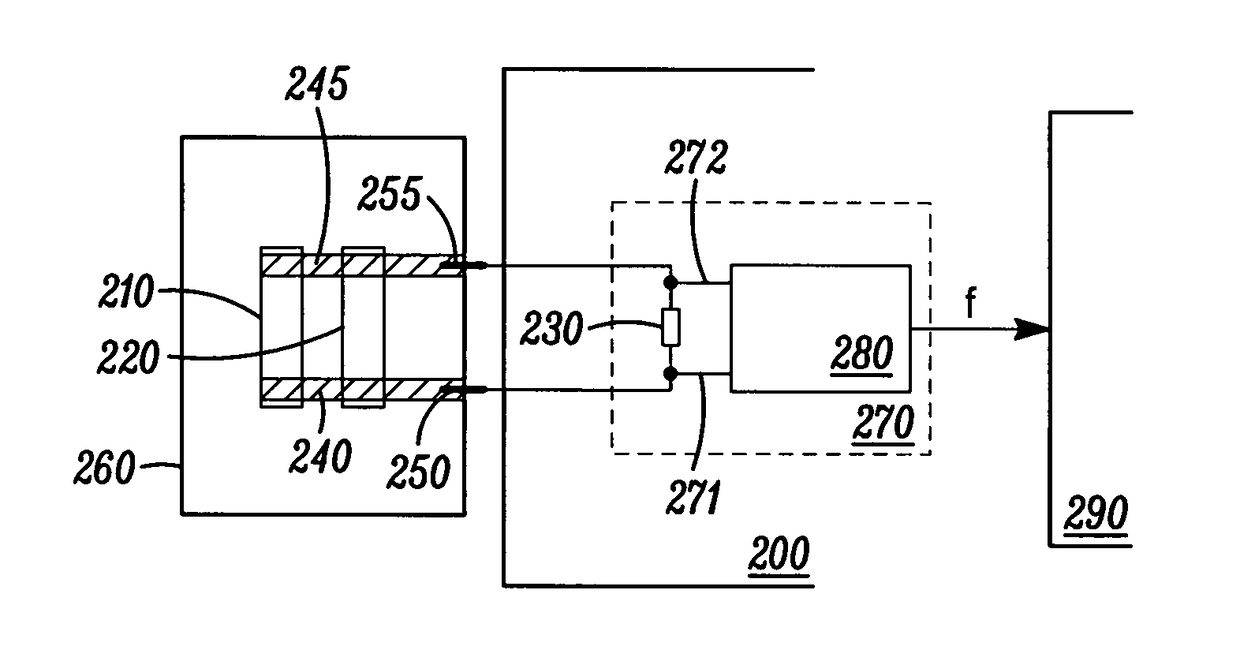
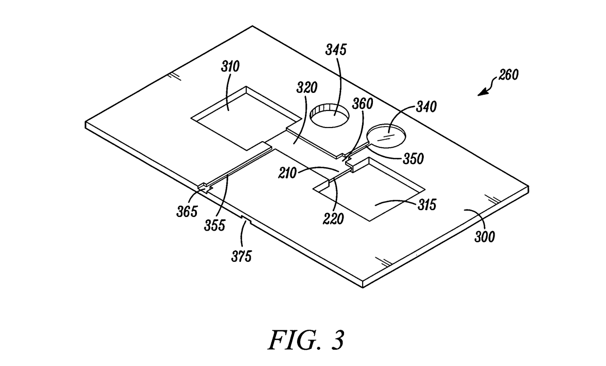
[0028]In order to calculate temperature corrected conductivity, two measurements are commonly required; conductivity (uncorrected for temperature) and the temperature at which the uncorrected conductivity was measured. A significant proportion of the cost associated with devices for measuring temperature corrected conductivity can be attributed to the extra components required for the accurate measurement of temperature. Significant cost savings can result if the need to measure temperature is eliminated. The present invention compensates for temperature without measuring temperature, and neither does it require the use of an on-board reference of known conductivity in order to calculate temperature.

[0029]The present invention provides increased accuracy over known devices which measure conductivity but do not correct for temperature. The present invention also improves over known methods of compensating for temperature variability in conductivity measurements without measuring temp...


PUM

PropertyMeasurementUnit
temperatureaaaaaaaaaa
operating temperatureaaaaaaaaaa

Abstract

The application relates to a conductivity measurement cell for measuring the concentration of a preselected biomarker or analyte in a body fluid, such as urine. In order to reduce the effect of sample dilution on measured concentration, the measured concentration can be normalized by a dilution factor, which can be determined from electrical conductivity. A test strip and measurement apparatus is disclosed for performing such normalized concentration measurement.

Description

CROSS REFERENCE TO RELATED APPLICATIONS[0001]This is the U.S. National Stage of International Application No. PCT / GB2009 / 002958, filed Dec. 24, 2009, which was published in English under PCT Article 21(2), which in turn claims priority from Great Britain Application No. 0823719.0, filed Dec. 31, 2008.FIELD OF INVENTION[0002]The present application relates to a conductivity measurement cell.BACKGROUND OF INVENTION[0003]It can be useful to measure the concentration of a preselected biomarker, or analyte, in a body-fluid such as urine. However, depending on the level of hydration of the patient, urine may be relatively dilute or concentrated and this variability in urine dilution can substantially affect the measured analyte concentration, preventing accurate diagnosis. In order to reduce the effect of the variability of urine sample dilution on the measured analyte concentration, the measured analyte concentration can be normalised by the urine dilution factor, which can be determined...

Claims


Application Information

Patent Timeline
Patent Type & Authority Patents(United States)
IPC IPC(8): G01N21/75G01N27/07G01N33/493H03K3/03
CPCG01N27/07G01N33/493H03K3/0315
Inventor BARNARD, JONATHAN D.CARLISLE, STEPHEN J.JONES, MALCOLM R.
Owner SPD SWISS PRECISION DIAGNOSTICS
Learn More