Image subtraction of illumination artifacts

Inactive Publication Date: 2005-07-28
ELECTRO SCI IND INC
View PDF13 Cites 14 Cited by
  • Summary
  • Abstract
  • Description
  • Claims
  • Application Information

AI Technical Summary

Benefits of technology

[0008] By digitally subtracting out the in-line on-axis illumination artifacts, a system so configured may be more sensitive to features of the object, as they will now be rendered in the image with less interference from the illumination artifacts. Additionally, a system so equipped may be operated at overall higher illumination levels without undue interference from illumination artifacts, increasing the domain of object types that may be inspected and the type of information about the object that may be extracted from the image.

Problems solved by technology

The problem with imaging systems such as these is that a portion of the illumination may be reflected by the optical elements between the illumination source and the object in a direction back toward the image plane where the illumination may register as an image artifact.

Method used


Image

  • Image subtraction of illumination artifacts
  • Image subtraction of illumination artifacts
  • Image subtraction of illumination artifacts

Examples


Embodiment Construction

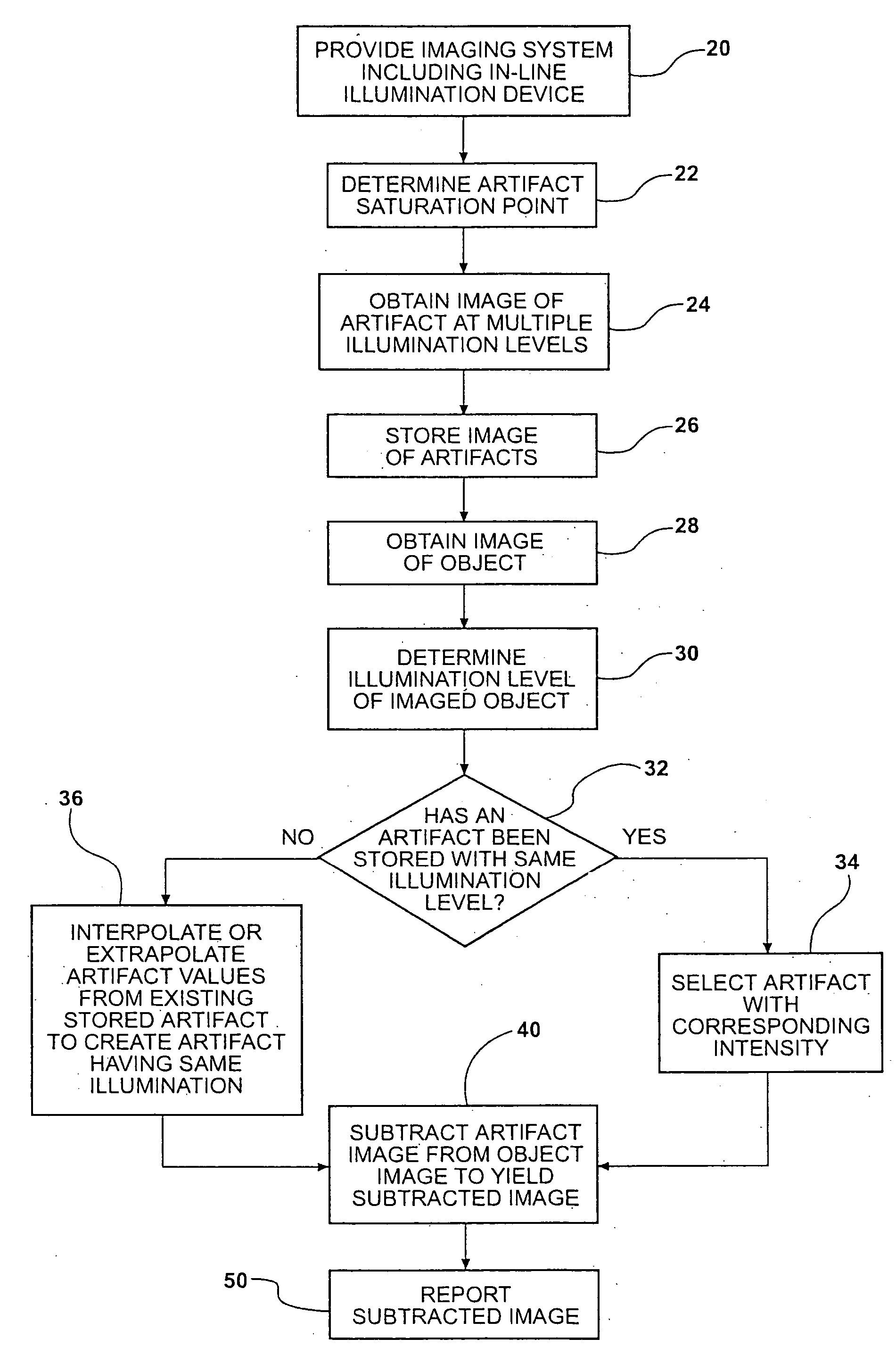
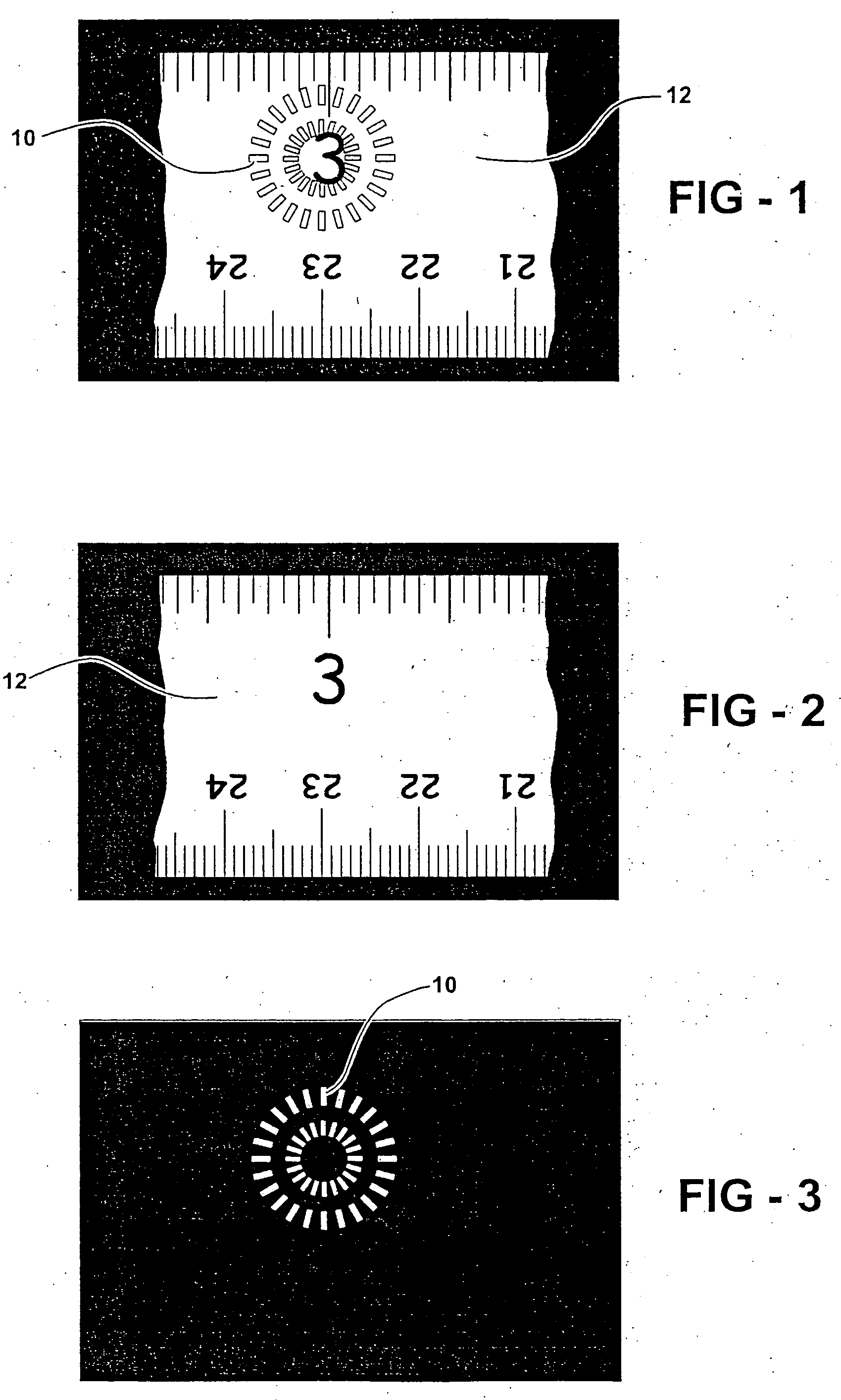
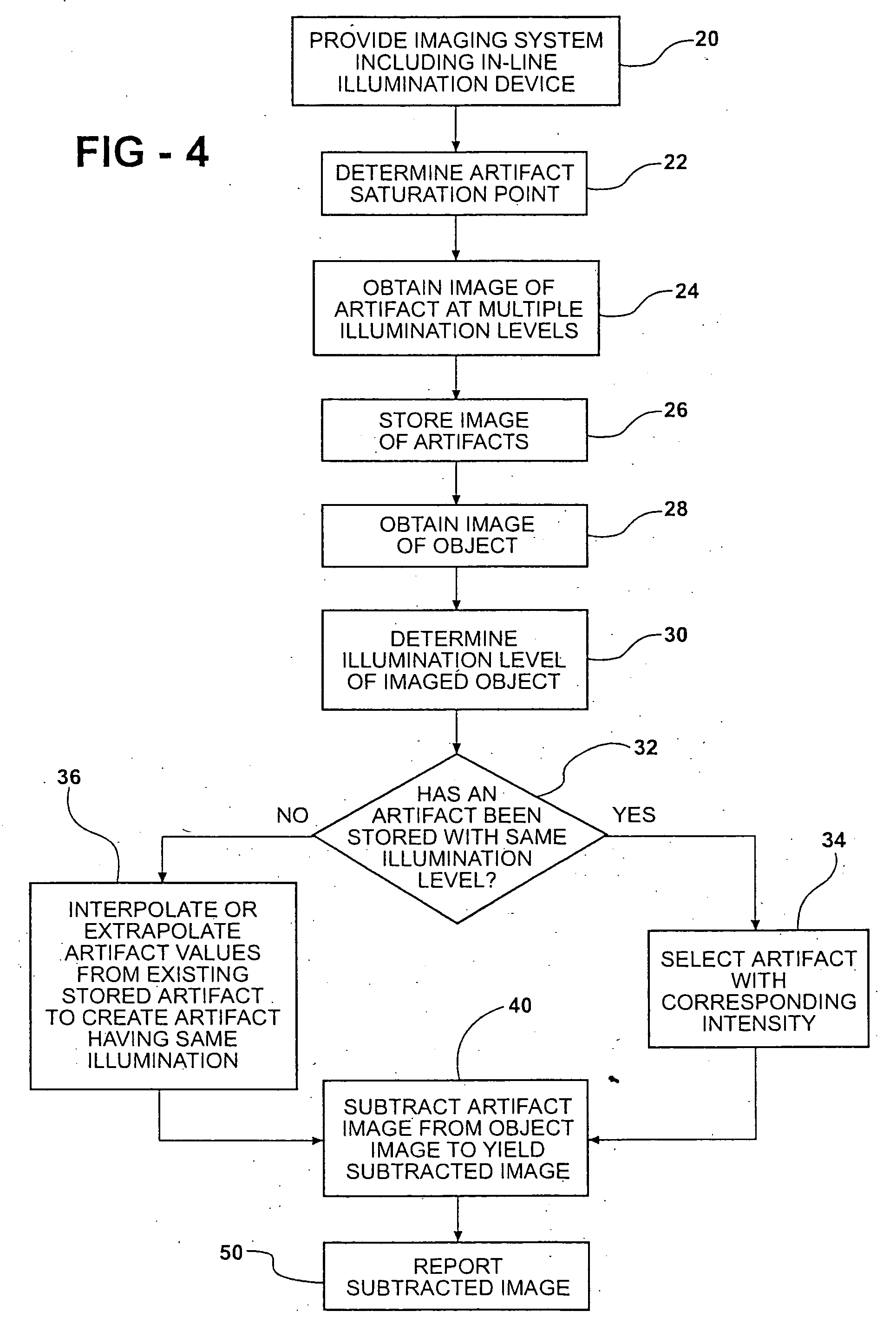
[0016] The invention involves digitally recording an illumination artifact associated with an imaging system. This artifact may then be later subtracted from subsequent images to remove the artifact from such images.

[0017] This invention is preferably utilized in combination with in-line illumination systems that can result in artifacts from internal reflections. One such in-line system is described in co-pending U.S. patent application Ser. No. 10 / 373,934, filed Feb. 26, 2003, which is incorporated herein in its entirety by reference. As shown in FIG. 5, such a system can include an imager 100 generally defined by an illumination source 118, an imaging lens 108, an electronic image detector such as a video camera 200, and a digital computing device (not shown) capable of accepting images electronically or optically from the electronic image detector and a set of instructions (a computer program) for digitally processing said image, typically for extracting information about the ob...


PUM


Abstract

A method of removing an artifact resulting from an in-line illumination device of an imaging system from an object image. It includes obtaining a first image of the artifact using a first artifact illumination level and imaging the object using the imaging system wherein the illumination device is using an object illumination level. An artifact image is independent of the object and has pixel values related to the illumination level. Thus, the artifact can be removed by subtracting respective pixel values of an artifact image from respective values of the object image on a pixel address-by-pixel address basis. Various illumination levels can be used to create more than one artifact image. The artifact image for the subtraction can be one of the images taken or can be a scaled image where an artifact image is scaled to the object illumination level.

Description

CROSS-REFERENCE TO RELATED APPLICATION [0001] This application claims the benefit of the priority date of co-pending U.S. Provisional Patent Application Ser. No. 60 / 538,914, which was filed on Jan. 23, 2004.BACKGROUND OF THE INVENTION [0002] In image processing, the goal is to examine an image of an object in order to extract some useful information about that object. This is most often done by analyzing variations in the brightness value of spatially separated elements of the image and comparing them to one another or comparing them to a priori determined values. [0003] It is not uncommon that there are brightness value variations within an image of an object that do not convey information about the object, but rather convey spurious information about the illumination system used to light the object or the imaging system used to optically form the image on the image sensor or about other aspects of the object's environment. When it is not possible to control the environment or the ...

Claims


Application Information

Patent Timeline
Patent Type & Authority Applications(United States)
IPC IPC(8): G06T5/00G06V10/145
CPCG06K9/2036G06V10/145G06T5/00G06T11/00G06T11/40
Inventor BALDWIN, LEO
Owner ELECTRO SCI IND INC
Why Eureka
Try Eureka