Optical fiber having high nonlinearity

a technology of optical fiber and nonlinearity, applied in the field of optical fiber, can solve the problems of unsuitable high-speed signal processing, complex production equipment, and deterioration of production yield, so as to increase the nonlinearity of optical fiber, and reduce the value of effective area

Active Publication Date: 2005-07-28
FURUKAWA ELECTRIC CO LTD
View PDF8 Cites 17 Cited by
  • Summary
  • Abstract
  • Description
  • Claims
  • Application Information

AI Technical Summary

Benefits of technology

[0049] As described above, it is understood from equation (1) that if the nonlinearity of the optical fiber is to be increased, the nonlinear refractive index n2 is required to be increased or the effective area Aeff reduced. The value n2, which is determined by the material, however, cannot be easily increased. It is more realistic, therefore, to reduce the value of the effective area Aeff of the optical fiber as far as possible. According to the first embodiment, the effective area Aeff of the optical fiber is determined as equal to or less than 15 μm2, or more preferably equal to or less than 12 μm2. As a result, an optical fiber having a larger nonlinear constant in which a nonlinear constant is equal to or more than 25×10−10 / W, or equal to or more than 40×10−10 / W is obtained at the wavelength of 1550 nm.
[0050] The value Aeff can be most effectively reduced by increasing the relative reflective index difference Δ1. A simulation is carried out for calculation of the proper relative reflective index difference Δ1. Table 2 shows the structural parameters other than Δ1 of the optical fiber used for the simulation. The parameters Δ2 and Δ3 are similar to the corresponding ones described above, and equations (2) to (5) apply. The examples 2-2 and 2-3 have no third core. TABLE 2Structural parameters of optical fiber used in simulation (2)Δ2Δ3%%D1 / D3D2 / D3αEXAMPLE 2-1−10.400.550.824EXAMPLE 2-2−1—0.55—4EXAMPLE 2-3−0.55—0.5—3
[0051]FIG. 5 shows the relation between the relative reflective index difference Δ1 and the effective area Aeff of the optical fiber having the structural parameters shown in Table 2. As shown in FIG. 5, the effective area Aeff reduces with the increase in the relative reflective index difference Δ1. Also, comparison between the examples 2-1 and 2-2 having the same structural parameters, the only difference being the presence or absence of the third core, shows that the addition of the third core having a higher refractive index than the cladding somewhat widens the effective area Aeff. Also, for the relative reflective index difference Δ1 of less than 1.5%, the effective area Aeff is large and the nonlinearity is comparatively small. If the optical fiber including the third core is to have the effective area Aeff of equal to or less than 15 μm2, therefore, at least the relative reflective index difference Δ1 is required to be equal to or more than 1.5%.
[0052] With the increase in relative reflective index difference Δ1, on the other hand, the cut-off wavelength shifts to long wavelength side. Once the relative reflective index difference Δ1 exceeds 5.0%, therefore, the great consideration paid for the cut-off wavelength to secure the single-mode operation of the optical fiber deteriorates the productivity. Further, a core having the relative reflective index difference Δ1 of more than 5.0% is actually very difficult to fabricate. Further, once the relative reflective index difference Δ1 exceeds 5.0%, the dispersion slope for 1550 nm increases, and in processing the optical signal, the dispersion greatly varies with different wavelengths in the neighborhood of 1550 nm. Therefore, the relative reflective index difference Δ1 is preferably between 1.5% and 5.0% inclusive.
[0053] The increase of the relative reflective index difference Δ2 to negative side makes it possible to reduce both the dispersion slope and the absolute value of the dispersion at 1550 nm at the same time, while the cut-off wavelength shifts to short wavelength side. As described above, the relative reflective index difference Δ1 of between 1.5% and 5.0% inclusive makes it possible to reduce the absolute value of.the dispersion slope to equal to or less than 0.03 ps / nm2 / km for the relative reflective index difference Δ2 of equal to or less than −0.1%, and to equal to or less than 0.01 ps / nm2 / km for the relative reflective index difference Δ2 of equal to or less than −0.7%. Also, the cut-off wavelength can be reduced to equal to or less than 1500 nm. To decrease the relative reflective index difference Δ2 to equal to or less than −1.4%, on the other hand, it is required to dope a great amount of fluorine and therefore the fabrication becomes difficult. The relative reflective index difference Δ2, therefore, is preferably between −1.4% and −0.1% inclusive, or more preferably between −1.4% and −0.7% inclusive.
[0054] When the relative reflective index difference Δ1 is equal to or more than 2.4% and the relative reflective index difference Δ2 is between −1.4% and −0.7% inclusive, as shown by examples 2-1 and 2-2 in FIG. 5, the effective area Aeff can be reduced to equal to or less than 11 μm2, and the nonlinear constant n2 / Aeff of equal to or more than 40×10−10 / W can be obtained. Also, the addition of the third core having a higher refractive index than the cladding somewhat expands the effective area Aeff, though still equal to or less than 12 μm2. In this case, the nonlinear constant n2 / Aeff of equal to or more than 35×10−10 / W can be obtained. When the relative reflective index difference Δ1 is equal to or less than 4.0% and the relative reflective index difference Δ2 is between −1.4% and −0.7% inclusive, a sufficiently high nonlinearity and low dispersion slope are obtained, and an optical fiber having a cut-off wavelength of equal to or less than 1500 nm is realized. Further, the addition of the third core increases the freedom of the refractive index profile, which leads to an improved yield, a higher productivity and a higher stability. More preferably, therefore, the relative reflective index difference Δ1 is set to between 2.4% and 4.0% inclusive and the relative reflective index difference Δ2 to between −1.4% and −0.7% inclusive.

Problems solved by technology

The process of converting an optical signal to an electrical signal and converting the electrical signal again to an optical signal, however, is unsuitable for high speed signal processing.
A very sophisticated technique is required to dope fluorine in a high-pressure environment and poses the problem that the production equipment is complicated and the production yield is deteriorated at the same time.

Method used


Image

  • Optical fiber having high nonlinearity
  • Optical fiber having high nonlinearity
  • Optical fiber having high nonlinearity

Examples


first embodiment

[0049] As described above, it is understood from equation (1) that if the nonlinearity of the optical fiber is to be increased, the nonlinear refractive index n2 is required to be increased or the effective area Aeff reduced. The value n2, which is determined by the material, however, cannot be easily increased. It is more realistic, therefore, to reduce the value of the effective area Aeff of the optical fiber as far as possible. the effective area Aeff of the optical fiber is determined as equal to or less than 15 μm2, or more preferably equal to or less than 12 μm2. As a result, an optical fiber having a larger nonlinear constant in which a nonlinear constant is equal to or more than 25×10−10 / W, or equal to or more than 40×10−10 / W is obtained at the wavelength of 1550 nm.

Relative Index Difference Δ1 and Δ2

[0050] The value Aeff can be most effectively reduced by increasing the relative reflective index difference Δ1. A simulation is carried out for calculation of the proper relat...

second embodiment

[0084] The optical fiber and the optical wavelength converter and the pulse compressor using the optical fiber are explained with reference to FIGS. 13 to 19.

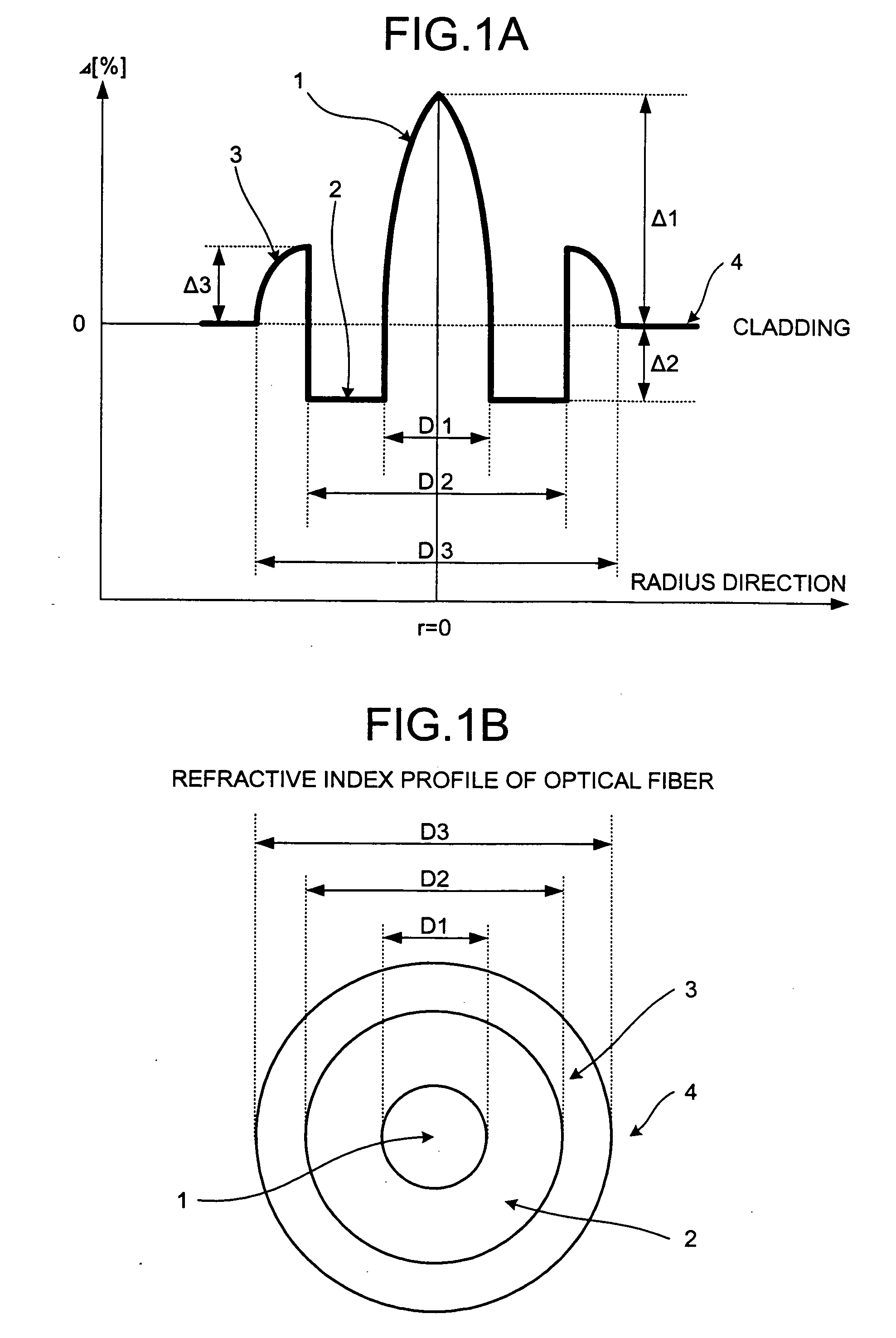
[0085]FIGS. 13A, 13B show an example of the optical fiber according to the second embodiment. FIG. 13A shows the refractive index profile of the optical fiber, and FIG. 13B shows a part of the cross section thereof. The outer line of the cladding 54 is not shown.

[0086] As shown in FIG. 13A, this optical fiber having what is called the W-type refractive index profile includes a first core 51 located at the central portion and having the a refractive index profile shown in equation (8), a second core 52 arranged on the outside of the first core 51 and having a lower refractive index than the first core 51, and a cladding 54 arranged on the outside of the second core 52 and having a higher refractive index than the second core 52. Also, the refractive index of the cladding 54 is higher than that of the pure silica glass indicate...


PUM


Abstract

An optical fiber includes a first core with a first refractive index located in a central portion of the optical fiber; a second core with a second refractive index located in an outer periphery of the first core; a third core with a third refractive index located in an outer periphery of the second core; and a cladding with a fourth refractive index located in an outer periphery of the third core, where among the refractive indices, the first one>the third one>the fourth one>the second one. The absolute value of dispersion at the wavelength of 1550 nm is not more than 20 ps/nm/km. The effective area at the wavelength is not more than 15 μm2. The nonlinear constant n2/Aeff at the wavelength of 1550 nm is equal to or more than 25×10−10/W.

Description

CROSS-REFERENCE TO RELATED APPLICATIONS [0001] This application claims the benefit of priority of Japanese Patent Applications No. 2004-017179 filed on Jan. 26, 2004 and No. 2004-125001 filed on Apr. 21, 2004, and the disclosures of which are incorporated herein by its entirely. BACKGROUND OF THE INVENTION [0002] 1) Field of the Invention [0003] This invention relates to an optical fiber having a superior nonlinearity and an optical signal processor using the optical fiber. [0004] 2) Description of the Related Art [0005] In recent years, demand has increased for the optical signal transmission higher in speed and capacity over a longer distance than ever before. This requires a signal processing technique for a high processing speed and long distance transmission of the optical signal. In one of the optical signal processing techniques, the optical signal is converted to an electrical signal, and the converted electrical signal is processed and restored again to the optical signal. ...

Claims


Application Information

Patent Timeline
Patent Type & Authority Applications(United States)
CPCG02B6/02028G02B6/02242G02B6/03644G02B6/0286G02B6/03627G02B6/02271
Inventor MIYABE, RYOHIROISHI, JIRO
Owner FURUKAWA ELECTRIC CO LTD
Why Eureka
Try Eureka