Objective lens and optical head device provided with the same

Inactive Publication Date: 2006-01-12
NIDEC SANKYO CORP
View PDF4 Cites 2 Cited by
  • Summary
  • Abstract
  • Description
  • Claims
  • Application Information

AI Technical Summary

Benefits of technology

[0022] When the objective lens of the present invention is used as described above, there exist a zero region where spherical aberration with respect to at least one optical recording medium is zero and/or an increase/decrease region where spherical aberration with respect to at least one optical recording medium increases or decreases toward zero in a range of R/3 to 2R/3 from an optical axis, in which the spherical aberr

Problems solved by technology

However, since unnecessary diffracted light is generated in the objective lens including the diffraction grating formed in the refraction surface, there is a problem of a loss of quantity of light, indicating a drop of transmittance of the laser light.
However, in the spherical aberration distribution shown in FIG. 8B, there exists a region where the spherical aberration increases in

Method used


Image

  • Objective lens and optical head device provided with the same
  • Objective lens and optical head device provided with the same
  • Objective lens and optical head device provided with the same

Examples


Example

EXAMPLE

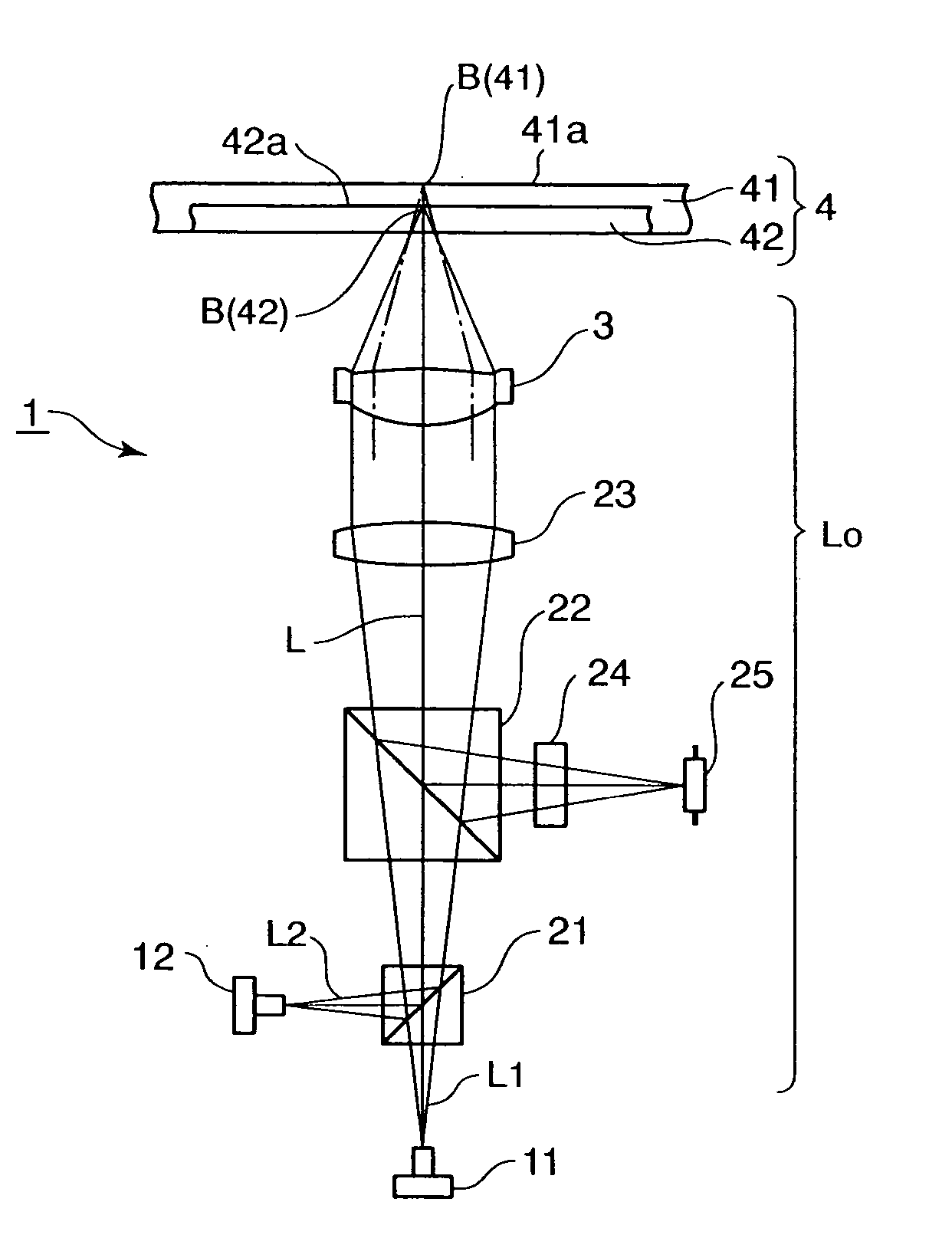
[0065] An example of an objective lens 3 will be described, to which the present invention is applied. Optical recording mediums in this example are a CD and a DVD.

Lens Design Data

[0066] Wavelengths λ1, λ2, numerical apertures NA1, NA2, and lens refractive indexes n1, n2 of the CD and the DVD, which are assumptions of lens design, are as follows. [0067] CD [0068]λ1=790 nm [0069] NA1=0.47 [0070] n1=1.537 [0071] DVD [0072] k2=660 nm [0073] NA2=0.6 [0074] n2=1.540

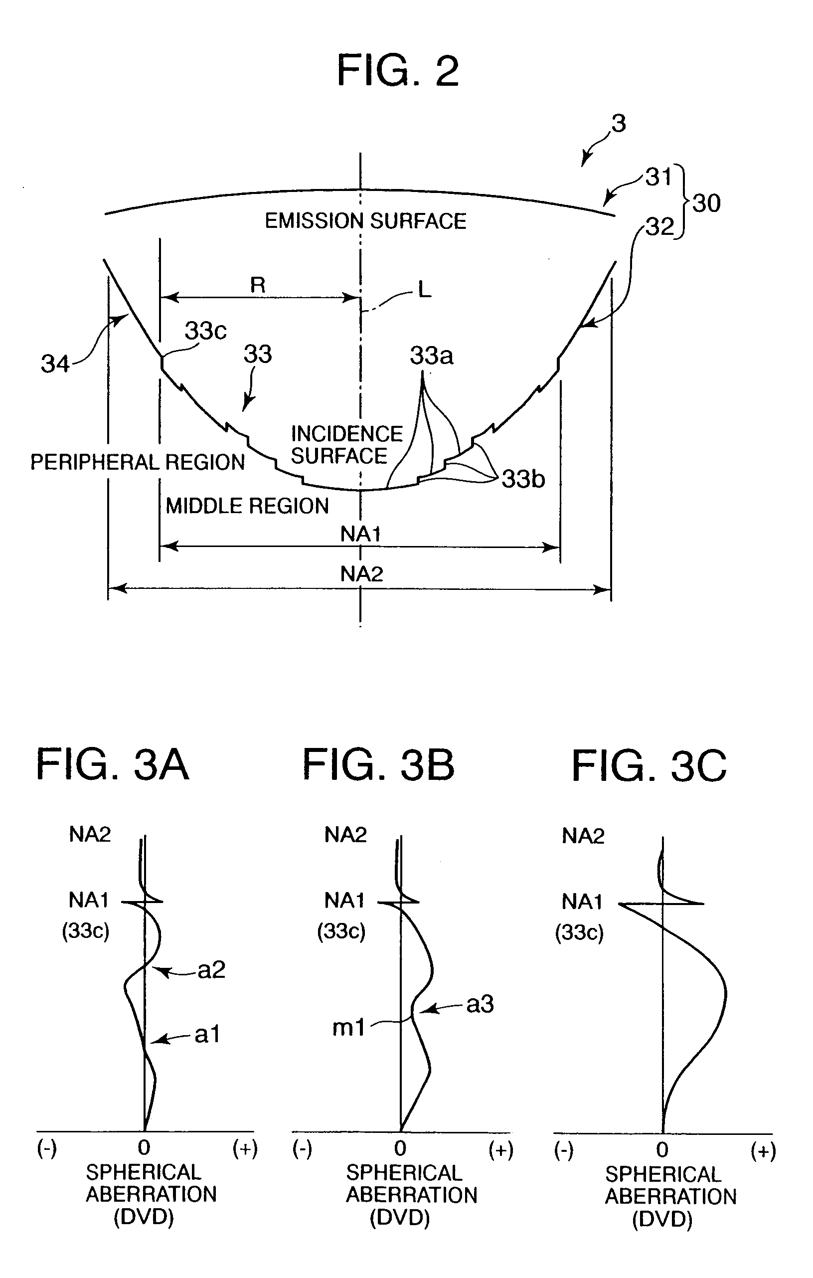
[0075] Lens design data of the example will be described hereinafter. In the following data, a surface interval is an interval between an incidence surface and an emission surface in an optical axis. A stepped portion of the incidence surface corresponds to a distance from an intersection between the incidence surface and the optical axis to an inner peripheral end of each annular refraction surface. Furthermore, an aspherical shape Z(r) of each annular refraction surface is rotationally symmetric, and is represent...


PUM


Abstract

An objective lens by which an effective value of spherical aberration with respect to an optical recording medium is reduced and in which a beam spot having a small diameter can be formed on a recording surface of the optical recording medium. An objective lens for an optical head device comprises a refraction surface provided with a middle region and a peripheral region, where, assuming that a distance from an optical axis to an outer peripheral portion of the middle region in a direction crossing the optical axis at right angles is R, there exist in a range of R/3 to 2R/3 from the optical axis, zero regions where the spherical aberration with respect to an optical recording medium turns to zero and/or an increase/decrease region where the spherical aberration with respect to the optical recording medium increases or decreases toward zero.

Description

CROSS-REFERENCE TO RELATED APPLICATIONS [0001] This application claims priority to Japanese Application No. 2004-203431 filed Jul. 9, 2004, which is incorporated herein by reference. FIELD OF THE INVENTION [0002] The present invention relates to an objective lens for use in an optical head device for recording and reproducing data with respect to optical recording mediums such as a CD and a DVD having different thicknesses of transparent substrates, using laser light having different wavelengths. The present invention also relates to an optical head device provided with the objective lens. BACKGROUND OF THE INVENTION [0003] An optical head device that records and reproduces data with respect to optical recording mediums having different thicknesses of transparent substrates for protecting recording surfaces, and different recording densities, using laser light having different wavelengths has been known in the art. Examples of the optical recording medium include a CD, a DVD and the...

Claims


Application Information

Patent Timeline
IPC IPC(8): G11B7/00
CPCG11B7/1275G11B7/1367G11B2007/0006G11B7/13922G11B7/1374
Inventor HAYASHI, KENICHIOKAMURA, TETSURO
Owner NIDEC SANKYO CORP
Why Eureka
Try Eureka