Motor driving apparatus

a technology of motor driving and control method, which is applied in the direction of motor/generator/converter stopper, dynamo-electric converter control, dc-ac conversion without reversal, etc., can solve the problems of increasing the ripple current flowing through increasing the size of the unit in its entirety, and increasing the size of the dc link capacitor. , to achieve the effect of reducing the effective value of current, reducing the capacity

Active Publication Date: 2006-03-30
MITSUBISHI ELECTRIC CORP
View PDF7 Cites 31 Cited by
  • Summary
  • Abstract
  • Description
  • Claims
  • Application Information

AI Technical Summary

Benefits of technology

[0009] According to the present invention, a period during which the output current of the DC / DC converter is zero is placed in the period during which the input current to the inverter is zero. As a result, the timing of the current pulses supplied from the DC / DC converter to the DC link capacitor and the timing of the current pulses supplied from the DC link capacitor to the inverter are matched, which makes it possible to reduce the effective values of the current flowing through the DC link capacitor, and to reduce the capacity of the DC link capacitor and the size of the apparatus.

Problems solved by technology

First, a power conversion unit constructed by integrating the inverter, DC / DC converter and DC link capacitor into a module to downsize the unit has a problem of increasing the ripple current flowing through the DC link capacitor because of interaction between the current pulses fed from the DC / DC converter to the DC link capacitor and the current pulses fed from the DC link capacitor to the inverter.
Second, a configuration that limits the ripple current per capacitor within a tolerance to maintain the life of the DC link capacitor has a problem of increasing the size of the DC link capacitor, which in turn increases the size of the unit in its entirety.

Method used


Image

  • Motor driving apparatus
  • Motor driving apparatus
  • Motor driving apparatus

Examples


embodiment 1

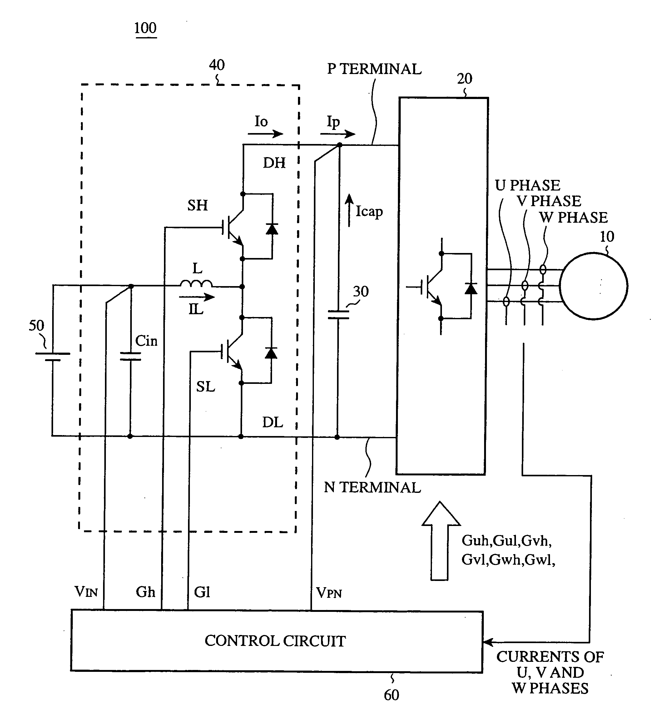
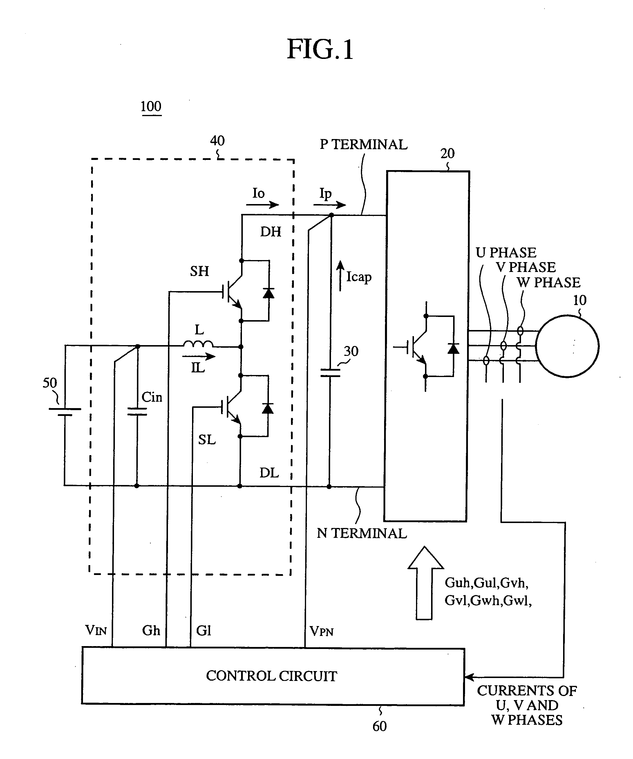
[0044]FIG. 1 is a block diagram showing a configuration of a motor driving apparatus 100 of an embodiment 1 in accordance with the present invention. The motor driving apparatus 100 is used for an electric vehicle or HEV. As shown in FIG. 1, the motor driving apparatus 100 includes a vehicle driving motor 10, a triangular wave comparing type PWM (Pulse Width Modulation) inverter 20, a DC link capacitor 30, a DC / DC converter 40, a high voltage battery (power supply) 50 of 100 V-300 V, and a control circuit 60.

[0045] The DC / DC converter 40 includes semiconductor switches (IGBT: Insulated Gate Bipolar Transistors) SH and SL, diodes DH and DL, a choke coil L, and an input voltage smoothing capacitor Cin.

[0046] The semiconductor switches SH and SL have their collector terminals connected to the cathode terminals of the diodes DH and DL, and their emitter terminals connected to the anode terminals of the diodes DH and DL.

[0047] The switch SH has its collector terminal connected to a fi...

embodiment 2

[0118]FIG. 18 is a block diagram showing a configuration of a motor driving apparatus 101 of an embodiment 2 in accordance with the present invention. In FIG. 18, the same reference numerals designate the same components as those of FIG. 1. The present embodiment 2 differs from the embodiment 1 in that the DC / DC converter 41 has a multiphase (2-phase in this case) scheme. The DC / DC converter 41 includes a DC / DC converter 41a and a DC / DC converter 41b. The multiphase DC / DC converter comprises a plurality of DC / DC converters connected in parallel, and operates the individual DC / DC converters with shifting their output phases. The chief merit of the multiphase DC / DC converter is that it can reduce the ripple current of the input voltage smoothing capacitor Cin and that of the DC link capacitor 30. Its demerit is that since it must control a plurality of DC / DC converters, the controller becomes complicated. Therefore the multiphase DC / DC converter is used to constitute a comparatively l...

embodiment 3

[0145] The configuration of the motor driving apparatus of the embodiment 3 is the same as that of the embodiment 2 as shown in FIG. 18. In the embodiment 2, the phases of the carrier signals of the DC / DC converters 41a and 41b are shifted by 180 degrees so that fundamental frequency of the output current Io of the DC / DC converter 41 becomes twice the carrier signal frequency of the DC / DC converter 41. In contrast, the embodiment 3 controls the DC / DC converter 41 in such a manner that the fundamental frequency of the output current Io of the DC / DC converter 41 is equal to the carrier signal frequency of the DC / DC converter 41.

[0146]FIG. 24 is a diagram illustrating the boosting operation of the DC / DC converter 41 of the embodiment 3. The reference symbol GZERO designates a voltage zero vector signal, which is placed at a high level when the inverter 20 is in the voltage zero vector mode, and at a low level at the remaining time periods. The reference symbol G11 designates an ON sig...


PUM


Abstract

A motor driving apparatus is provided which can minimize ripple current flowing through a DC link capacitor, and downsize the motor driving apparatus. It synchronizes the frequency of the inverter carrier signal for driving an inverter with the frequency of the DC/DC converter carrier signal for driving a DC/DC converter, and carries out control in such a manner that the center of a period during which the input current of the inverter is zero and the center of a period during which the output current of the DC/DC converter is zero are matched.

Description

BACKGROUND OF THE INVENTION [0001] 1. Field of the Invention [0002] The present invention relates to a control method of a motor driving apparatus using a DC / DC converter and an inverter. [0003] 2. Description of Related Art [0004] As an example of a conventional motor driving apparatus used for an electric vehicle or HEV (Hybrid Electric Vehicle), a motor driving apparatus disclosed in Relevant Reference 1 is known. The motor driving apparatus includes a motor, an inverter for converting DC power to AC power, a high voltage battery, a DC / DC converter and a DC link capacitor. The DC / DC converter boosts the voltage fed from a high voltage battery and supplies the DC power to the inverter during power running, and decreases the voltage of the DC power output from the inverter and supplies it to the high voltage battery during regenerative running. The DC link capacitor, which includes a plurality of capacitors, is interposed between the DC / DC converter and the inverter to smooth the D...

Claims


Application Information

Patent Timeline
Patent Type & Authority Applications(United States)
IPC IPC(8): H02M5/45H02M7/48H02P27/06
CPCH02M1/14H02M3/158Y10S388/90H02M2001/007H02M7/53873H02M1/007
Inventor OKUDA, TATSUYAURAKABE, TAKAHIROKURAMOTO, YUUJI
Owner MITSUBISHI ELECTRIC CORP
Why Eureka
Try Eureka