Image heating apparatus and heater for use therein
- Summary
- Abstract
- Description
- Claims
- Application Information
AI Technical Summary
Benefits of technology
Problems solved by technology
Method used
Image
Examples
embodiment 1
[0050] (1) Example of Image Forming Apparatus
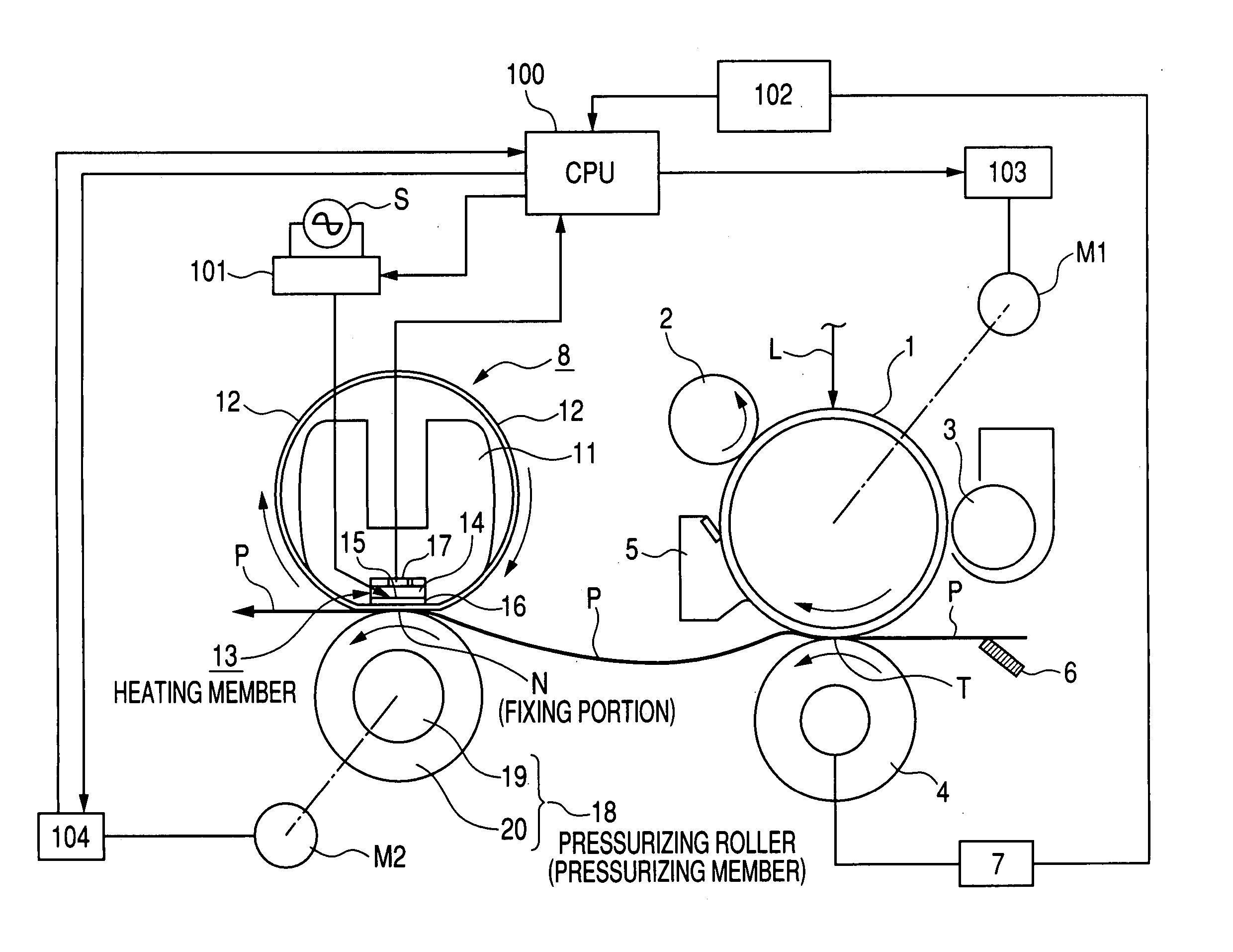
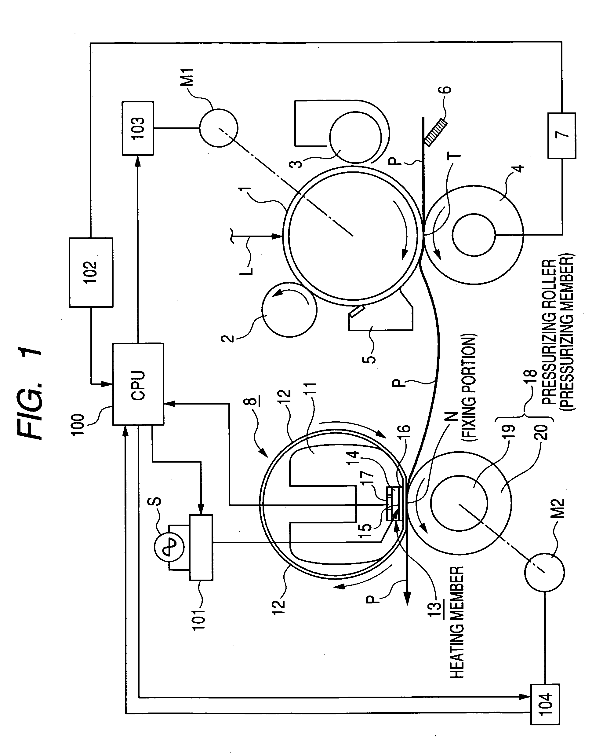
[0051]FIG. 1 is a schematic view showing a configuration of an image forming apparatus. The image forming apparatus of the present embodiment is a copying apparatus or a printer utilizing an electrophotographic process of transfer type. In the image forming apparatus of the present embodiment, a largest usable recording material is of a letter size (216×279 mm), and the recording material of such letter size can be conveyed with the longer side (279 mm) thereof parallel to the conveying direction. Also conveying of the recording material is executed taking, as a reference, a longitudinal center of a heat generating resistor of a fixing apparatus to be explained later.
[0052] An electrophotographic photosensitive member 1 of a drum shape (hereinafter represented as photosensitive drum) serves as a latent image bearing member and is rotated with a predetermined process speed, in a clockwise direction as indicated by an arrow. A main motor ...
embodiment 2
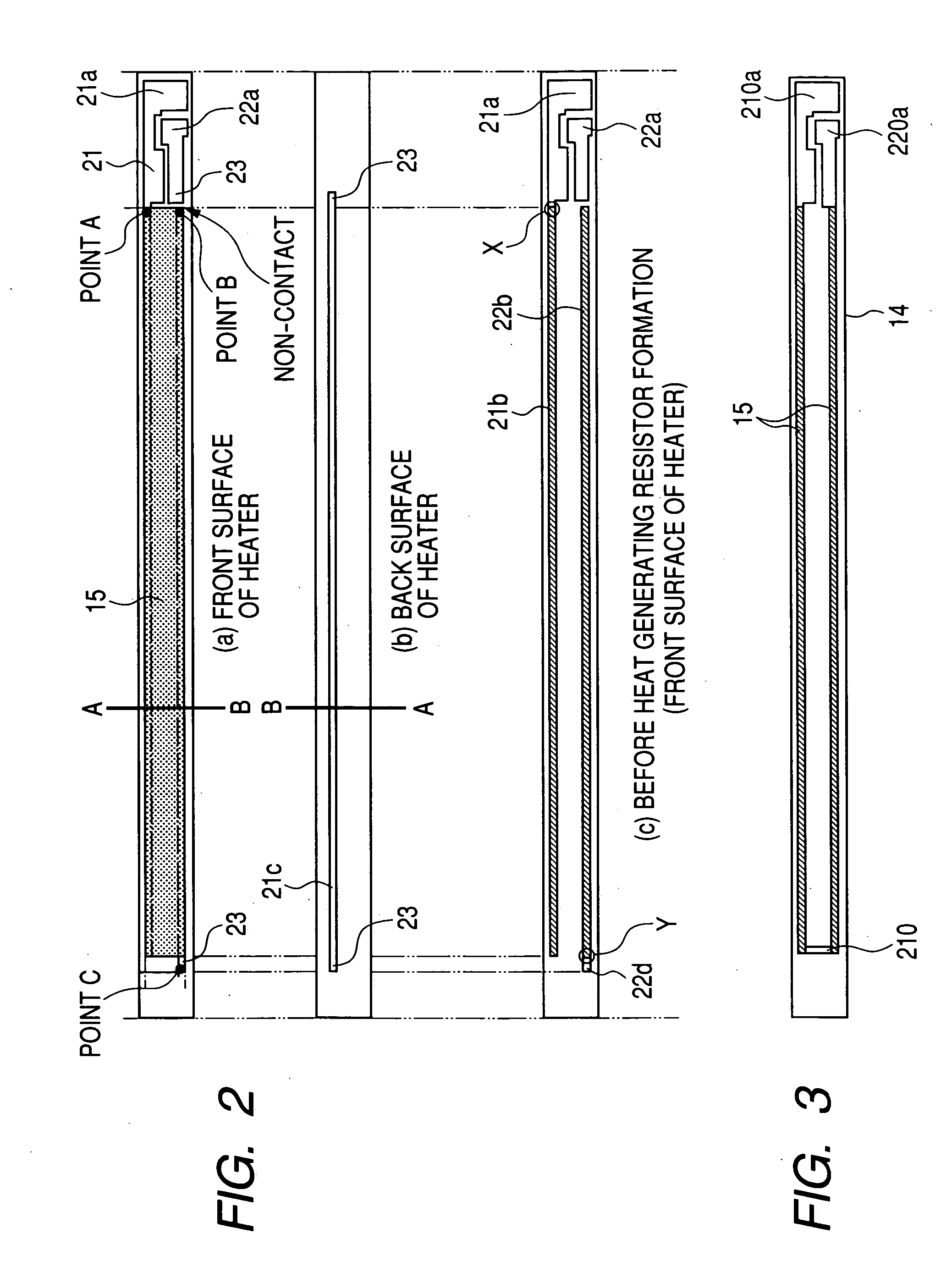
[0097] In the embodiment 1, as explained in the foregoing, within the second area 21b of the first electrode 21, a portion electrically closest to the first area 21a of the first electrode 21 (a portion X in FIG. 2) is provided in the vicinity of an end (right-hand end in FIG. 2) of the substrate 14 in the longitudinal direction thereof, and, within the second area 22b of the second electrode 22, a portion electrically closest to the first area 22a of the second electrode 22 (a portion Y in FIG. 2) is provided in the vicinity of the other end (left-hand end in FIG. 2) of the substrate 14 in the longitudinal direction thereof. Thus, inn the heater of the embodiment 1, the current entrances from the electrodes to the heat generating resistor are separated at both ends of the substrate in the longitudinal direction thereof.
[0098] On the other hand, in the embodiment 2, within the second areas 21b, 22b of the first electrode 21 and the second electrode 22, portions electrically closest...
embodiment 3
[0114] In the following, there will be explained a third embodiment of the present invention.
[0115] In FIG. 13, (a) and (b) are magnified views respectively of a top surface and a rear surface of a heater 13 in an image heating apparatus of the present embodiment. On a substrate 14, electrodes and a heat generating resistor have shapes and functions basically same as those in the embodiment 1 shown in FIG. 2.
[0116] In the present embodiment, there is defined a relationship between a resistance value Rt (hereinafter called total resistance value) from a portion, within the second area of the first electrode, electrically closest to the first area of the first electrode, to a portion, within the second area of the second electrode, electrically closest to the first area of the second electrode, and a resistance value Rc of the second area of an electrode.
[0117] As already explained in the embodiment 1, when the heater is at the set temperature (fixing temperature) of the fixing pro...
PUM
 Abstract
Description
Claims
Application Information
 - R&D
- Intellectual Property
- Life Sciences
- Materials
- Tech Scout
- Unparalleled Data Quality
- Higher Quality Content
- 60% Fewer Hallucinations
Browse by: Latest US Patents, China's latest patents, Technical Efficacy Thesaurus, Application Domain, Technology Topic, Popular Technical Reports.
© 2025 PatSnap. All rights reserved.Legal|Privacy policy|Modern Slavery Act Transparency Statement|Sitemap|About US| Contact US: help@patsnap.com


