Belt fixing unit and image forming toner for use in the fixing unit

a technology for fixing units and belts, which is applied in the field of belt fixing units and image forming toner for use in the belt fixing units, can solve the problems of inability to use high-speed image forming apparatuses, linear speed of the fixing and pressing rollers is relatively slow, and the length of the fixing nip is inherently limited, so as to reduce or eliminate the

Active Publication Date: 2005-07-28
RICOH KK
View PDF6 Cites 85 Cited by
  • Summary
  • Abstract
  • Description
  • Claims
  • Application Information

AI Technical Summary

Benefits of technology

[0022] Accordingly, it is an object of the present invention to provide a belt fixing unit, an image forming apparatus incorporating the fixing unit, and a toner material suitably used in the fixing unit having most, if not all, of the advantages and features of similarly employed units and materials, while reducing or eliminating many of the aforementioned disadvantages.

Problems solved by technology

Since the fixing nip in the roller fixing method is formed with the rollers contacting each other, the length of the fixing nip is inherently limited, and the linear speed of the fixing and the pressing rollers is relatively slow.
Therefore, this method is not suitable for use in a high speed image forming apparatus.
In order to increase the nip width over a certain level in the roller fixing method, the roller diameter has to be larger, undesirably increasing the overall size of the image forming apparatus.
The belt fixing method, however, has a drawback, as discussed next.
If the deformation is not easily restored after the system resumes operation, this deformation may cause several problems such as, for example, the irregularity in the rotation of the fixing belt and in the adherence to the heating roller.
This may result in uneven heat conduction and concomitant results of partial underdevelopment among others.
Such reinforcement, however, will result in the increase not only in the volume of the rollers but also in heat capacity of the apparatus as a whole.
As a result, since the time for heating increases, not only accessibility and serviceability worsen, but, the overall energy consumption of the apparatus increases.

Method used


Image

  • Belt fixing unit and image forming toner for use in the fixing unit
  • Belt fixing unit and image forming toner for use in the fixing unit
  • Belt fixing unit and image forming toner for use in the fixing unit

Examples


Embodiment Construction

[0045] In the detailed description which follows, specific embodiments of a belt fixing unit, an image forming apparatus, and a toner suitably used in the fixing unit are described. It is understood, however, that the present disclosure is not limited to these embodiments. For example, it is appreciated that the use of the structure, component, and properties described may also be adaptable to any form of imaging systems. Other embodiments will be apparent to those skilled in the art upon reading the following description.

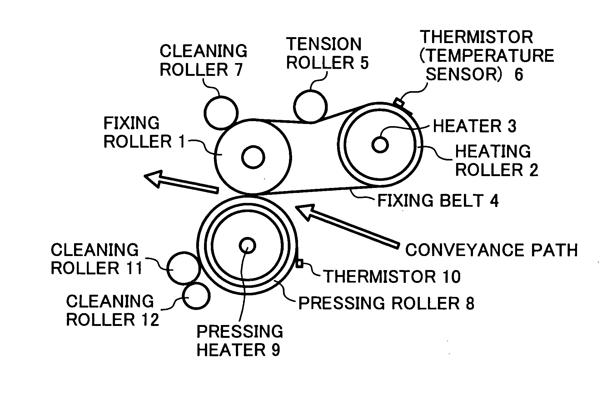
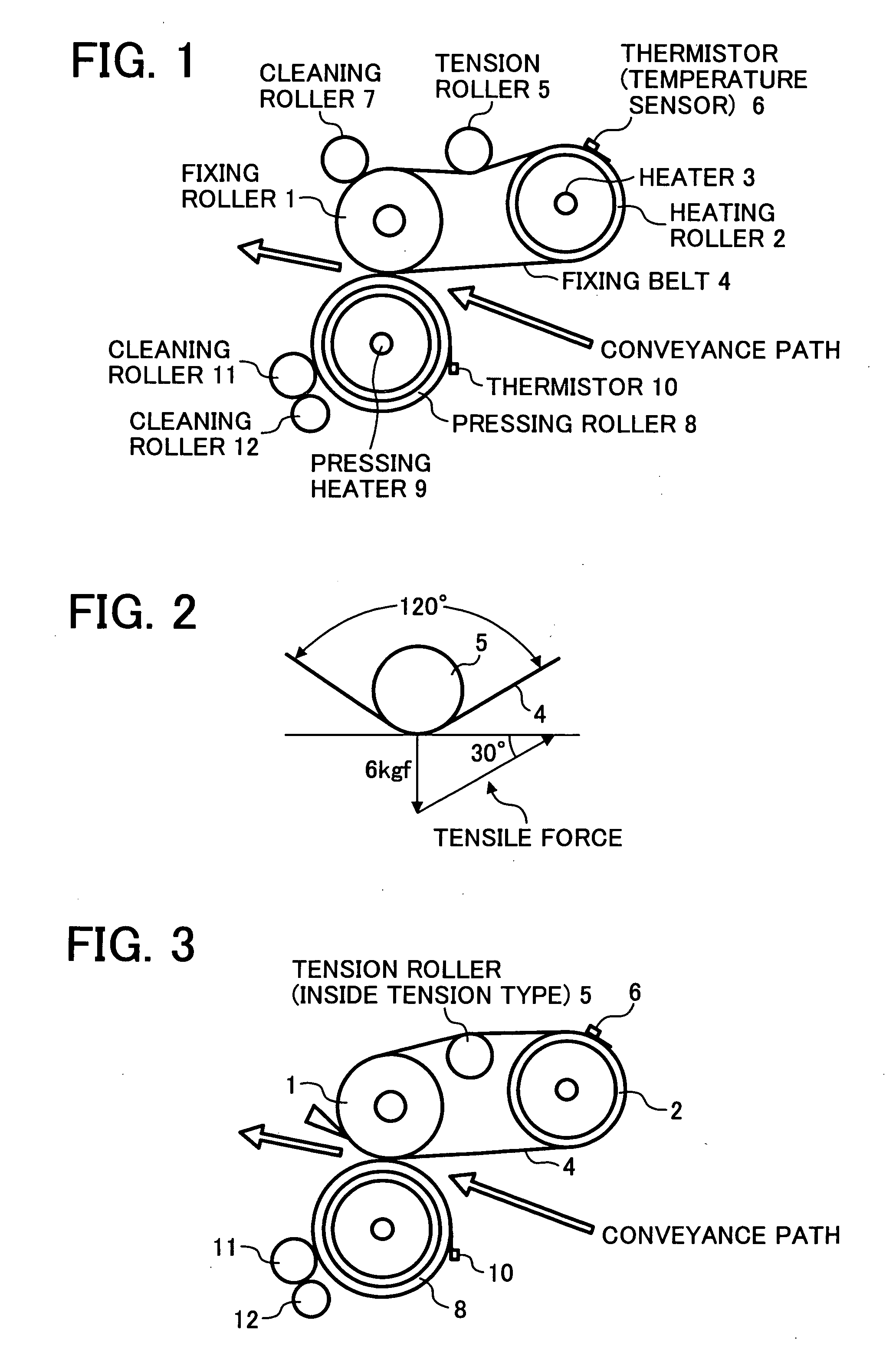
[0046] The major portions of a belt fixing unit according to one embodiment of the present invention are shown in FIG. 1.

[0047] Referring to FIG. 1, the belt fixing unit include a fixing roller 1, a heating roller 2 housing therein a heater 3, a fixing belt 4 spanned around at least the fixing roller 1 and the heating roller 2, a tension roller 5 disposed so as to be pressed against the fixing belt 4 from the outside for suitably adjusting the tension of the fixi...


PUM


Abstract

A belt fixing unit, an image forming apparatus, and a toner material are disclosed capable of obviating undesirable fixing belt deformation and low image quality. The belt fixing unit includes a fixing roller, a heating roller, a fixing belt, and a pressing roller in contact with the fixing roller to form a fixing nip having the fixing belt intervening there between, the fixing belt including at least a base member formed of a heat-resisting resin having a thickness of 90 μm or smaller and acted upon by a tensile force of 0.49 N / mm or less. The toner is a low-melting point toner formed by subjecting a toner preparatory solution containing at least a prepolymer having a functional group containing a nitrogen atom, a polyester, a colorant and a releasing agent dispersed in an organic solvent to extension and / or crosslinking reactions in an aqueous medium.

Description

CROSS REFERENCE TO RELATED APPLICATIONS [0001] This application claims priority to Japanese application No. 2003-429895, filed on Dec. 25, 2003, the disclosure of which is incorporated by reference herein in its entirety. BACKGROUND OF THE INVENTION [0002] 1. Field of the Invention [0003] The invention relates to a belt fixing unit, an image forming apparatus incorporating the fixing unit, and a toner material suitably used in the fixing unit capable of obviating undesirable fixing belt deformation and concomitant results of partial underdevelopment of electrophotographic images. [0004] 2. Discussion of the Background [0005] As to an image fixing process undertaken in an image forming apparatus making use of electrophotography and electrostatic recording, a heat roller fixing unit is known, including a fixing roller having an internal heat source and a pressing roller pressed against the fixing roller. An image transfer sheet carrying an unfixed toner image is conveyed through a fix...

Claims


Application Information

Patent Timeline
Patent Type & Authority Applications(United States)
IPC IPC(8): G03G9/087G03G9/08G03G15/20
CPCG03G15/2064G03G2215/2016G03G2215/2083G03G2215/2041G03G2215/2032G03G15/2053
Inventor SATOH, MASAHIKOTOMITA, MASAMISOGA, SETSUOYOSHIKAWA, TAKAHIROHACHISUKA, TOSHIHARUKOHIRA, YASUHIROOMURA, KENSHINSHI, AKIRAIWAYA, NAOKI
Owner RICOH KK
Why Eureka
Try Eureka