Hollow fan blade for gas turbine engine

a gas turbine engine and fan blade technology, applied in the field of hollow fan blades for gas turbine engines, can solve the problems of increasing time and cost of operation, skins that do not possess the robustness to withstand this load, and skins that undergo significant compressive loading, so as to reduce time and cost of manufacturing and improve durability.

Active Publication Date: 2005-07-28
RAYTHEON TECH CORP
View PDF6 Cites 15 Cited by
  • Summary
  • Abstract
  • Description
  • Claims
  • Application Information

AI Technical Summary

Benefits of technology

[0008] The present invention provides a hollow fan blade with internal cavity and rib geometry with improved durability that permits the bonding and forming to be performed without the need for gas pressurization. This reduces the time and cost of manufacturing the hollow fan blade.
[0009] The ability to form the hollow fan blade of the present invention without gas pressurization is a result of the cavity and rib geomet...

Problems solved by technology

These skins undergo significant compressive loading during the bonding and forming operations.
At elevated temperatures, these skins do no possess the robustness to withstand this loading, and deform by sagging or droopin...

Method used


Image

  • Hollow fan blade for gas turbine engine
  • Hollow fan blade for gas turbine engine
  • Hollow fan blade for gas turbine engine

Examples


first embodiment

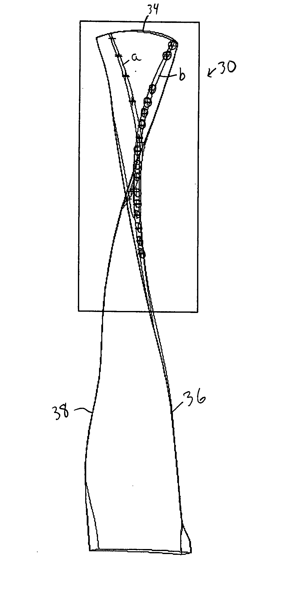
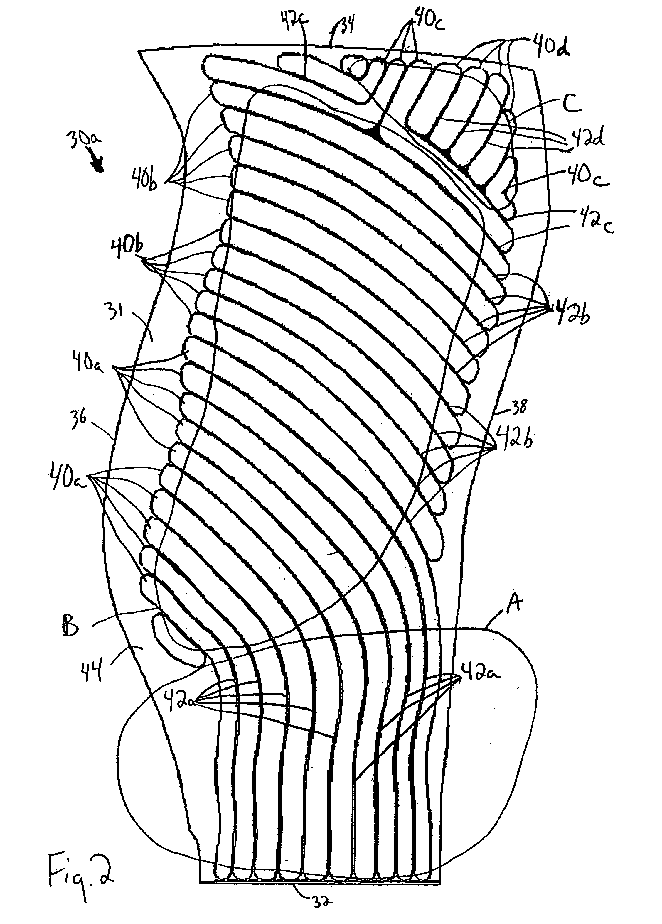
[0026] one fan blade detail half 30a is shown in FIG. 2. The other fan blade detail half 30b would be complementary. The fan blade detail half 30a comprises a substrate 31, preferably Titanium, having a root edge 32 opposite a tip 34 and a leading edge 36 opposite a trailing edge 38. The fan blade detail half 30a includes Region A, which is approximately the radially inner-most third adjacent the root edge 32. Region B extends from Region A toward the tip 34, excluding a corner area adjacent the tip 34 and trailing edge 38, which is Region C.

[0027] In order to reduce weight while still maintaining the necessary stiffness and strength, a plurality of elongated continuous cavities 40a-d are machined into the interior surface of the substrate 31. The cavities 40a-d are spaced from one another to form a plurality of continuous, non-intersecting ribs 42a-d. Alternatively (or additionally), the ribs 42a-d are superplastically formed. Throughout this description, the reference numeral 40 m...

second embodiment

[0039]FIG. 10 illustrates a fan blade detail half 60a that could be used in the turbine engine 10 of FIG. 1. Again, the other fan blade detail half (not shown) would be complementary. The fan blade detail half 60a comprises a substrate 61, preferably Titanium, having a root edge 62 opposite a tip 64 and a leading edge 66 opposite a trailing edge 68. A plurality of elongated continuous cavities 70 are machined into or superplastically or otherwise formed on the interior surface of the substrate 61 in the manner described above with respect to FIGS. 3 and 4. The cavities 70 are spaced from one another to form a plurality of continuous non-intersecting ribs 72, 73. In this embodiment the spacing between ribs is held constant throughout.

[0040] In the second embodiment, the cavities 70a-d extend continuously alongside ribs 72a-e and ribs 73. The cavities 70a-d also extend around freestanding ends 74 of some of the ribs 72a-e, thereby reducing the number of cavities 70a-d.

[0041] The fan ...


PUM

PropertyMeasurementUnit
Temperatureaaaaaaaaaa
Weightaaaaaaaaaa
Thicknessaaaaaaaaaa

Abstract

A hollow fan blade for turbo fan gas turbine engines is formed of two separate detail halves. Each detail half has a plurality of cavities and ribs machined out to reduce weight. These detail halves are subsequently bonded and given an airfoil shape in the forming operation. The present invention provides a hollow fan blade with internal cavity and rib geometry with improved durability that permits the bonding and forming to be performed without the need for gas pressurization. The ability to form the hollow fan blade of the present invention without gas pressurization is a result of the cavity and rib geometry and the orientation of the ribs. The ribs are tapered and transition into a compound radius of the floor that simulates the classical arch design element. The orientation of the ribs is generally in a parallel plane with the load vector that results from forming loads during the pre-form and final form operations. This orientation provides compressive stress transfer into the ribs and away from the concave and convex skins. The rib spacing is controlled where ribs can not be held in a parallel plane with the load vector.

Description

BACKGROUND OF THE INVENTION [0001] The present invention relates generally to gas turbine engines and more particularly to an improved hollow fan blade for a gas turbine engine. [0002] A gas turbine engine, such as a turbo fan engine for an aircraft, includes a fan section, a compression section, a combustion section and a turbine section. An axis of the engine is centrally disposed within the engine and extends longitudinally through the sections. The primary flow path for working medium gases extends axially through the sections of the engine. A secondary flow path for working medium gases extends parallel to and radially outward of the primary flow path. [0003] The fan section includes a rotor assembly and a stator assembly. The rotor assembly of the fan includes a rotor disc and plurality of radially extending fan blades. The fan blades extend through the flow path and interact with the working medium gases and transfer energy between the fan blades and working medium gases. The...

Claims


Application Information

Patent Timeline
IPC IPC(8): B23P15/04F01D5/14F01D5/18F02C3/06F02C7/16F04D29/32
CPCB23P15/04F01D5/147F01D5/18F04D29/324Y10T29/49339Y02T50/676F05D2220/36F05D2230/10F05D2220/324Y02T50/671Y02T50/60
Inventor WHITESELL, DANIEL J.WEISSE, MICHAEL A.PALAZZINI, CHRISTOPHER MARK
Owner RAYTHEON TECH CORP
Why Eureka
Try Eureka