Method and apparatus for dispensing liquids in a micro-grid pattern

a micro-grid pattern and liquid technology, applied in the direction of analytical instruments, laboratory glassware, chemical indicators, etc., can solve the problems of inability to simultaneously, parallel spotting in the sub-mm grid spacing, and inability to accurately predict the shape of the grid,

Inactive Publication Date: 2005-07-28
SIEMENS AG
View PDF27 Cites 8 Cited by
  • Summary
  • Abstract
  • Description
  • Claims
  • Application Information

AI Technical Summary

Benefits of technology

[0013] In an embodiment of the invention, the macrocapillaries may be advantageously coupled to the microcapillaries via a coupling mechanism that can be disconnected. In this arrangement, at least one pump device may be connected to each macrocapillary, and there may be a controller for controlling the flow of liquid. The overall arrangement has a robot-controlled device which allows the mobility and therefore accurate positioning of the system with the microcapillary tips separated in the x, y and z axes.

Problems solved by technology

Contact methods are unsuitable for sensitive surfaces.
However, they are unsuitable for simultaneous, parallel spotting in the sub-mm grid spacing.
However, when the flying drops leave the nozzle, their direction of flight may scatter, thereby leading to geometric inaccuracies through satellite formation in individual cases even to the extent of contaminating neighboring positions.
Furthermore, methods with free-flying drops are greatly restricted in terms of the viscosity and surface tension of the spotable substances which can be selected.
However, since this method is a contactless method with free-flying drops, the same drawbacks apply as have already been listed above: In particular, drift, satellites, restrictions in viscosity and surface tension may arise.

Method used


Image

  • Method and apparatus for dispensing liquids in a micro-grid pattern
  • Method and apparatus for dispensing liquids in a micro-grid pattern
  • Method and apparatus for dispensing liquids in a micro-grid pattern

Examples


Embodiment Construction

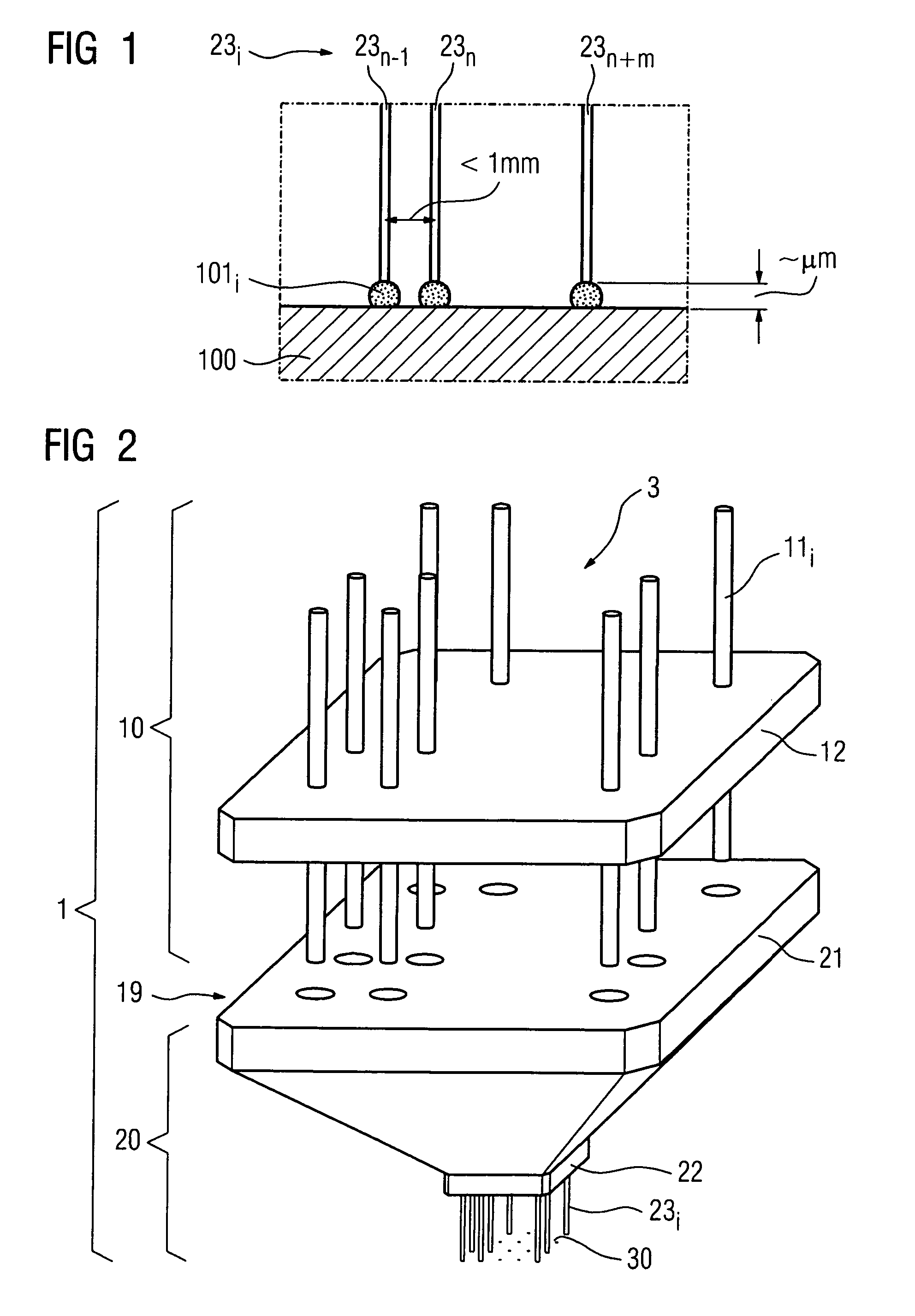
[0020] For use in in-vitro diagnostics, an array of individual spots may be produced for a biochip. The individual spots are located on a substrate and include a capture device, on which the molecules can dock in accordance with the key / lock principle during the subsequent biochemical analysis. A suitable spotting solution may be used to produce the spot array. Furthermore, technical devices / methods for dispensing may be used to discharge the spots, for example at a micrometer spacing, onto the substrate.

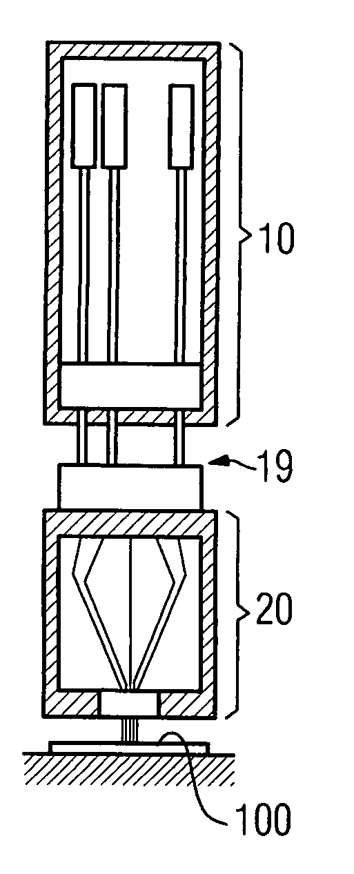
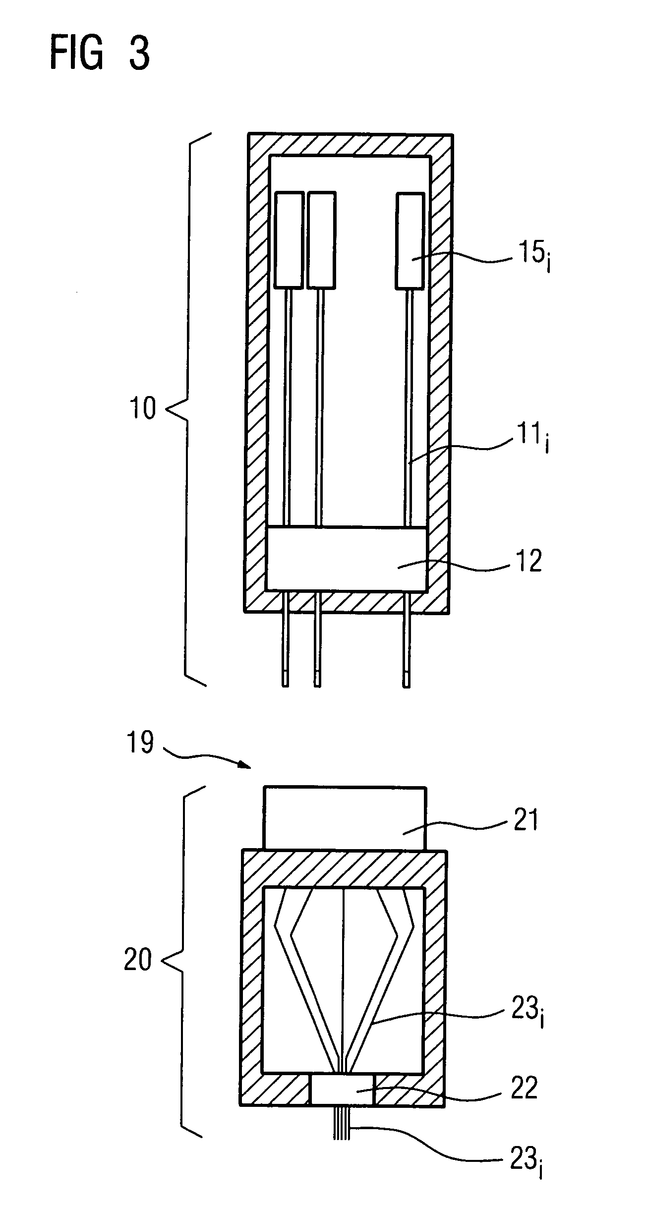
[0021] For the latter purpose, a method may be provided for the simultaneous, parallel dispensing of different liquids in a micro-grid pattern, using an arrangement of macrocapillaries in a macro-grid pattern which are used to load the microcapillaries. This purpose may be served by the apparatus described below having microcapillaries which are held in the dispensing grid pattern by a microelement. The inlet openings of the microcapillaries and the outlet openings of the macrocapi...


PUM

PropertyMeasurementUnit
volumeaaaaaaaaaa
volumesaaaaaaaaaa
pressureaaaaaaaaaa

Abstract

An intention is for liquids to be dispensed in a micro-grid pattern, i.e. at grid spacings of less than 1 mm. Either a single liquid at a plurality of spots or a plurality of different liquids are released to the substrate simultaneously from microcapillaries by way of a simultaneous capillary/liquid/substrate contact, but without capillary/substrate contact. In the associated apparatus, by way of a macro-head and individual macrocapillaries, which are arranged in a macro-grid pattern, the liquid is transferred, via a coupling location, into a dispensing head with microcapillaries. The macrocapillaries are coupled to the microcapillaries, which transfer the liquid into the micro-grid pattern.

Description

[0001] The present application hereby claims priority under 35 U.S.C. §119 on German patent application numbers DE 10361399.4 filed Dec. 29, 2003, the entire contents of which is hereby incorporated herein by reference. FIELD OF THE INVENTION [0002] The invention generally relates to a method for dispensing liquids in a micro-grid pattern. In particular, it relates to a method for the simultaneous, parallel dispensing (spotting) of different quantities of liquid in the range of <<1 μl in a grid spacing of <1 mm. In addition, the invention also generally relates to the associated apparatus for carrying out the method. BACKGROUND OF THE INVENTION [0003] Array technologies are increasingly being used in molecular diagnostics. Hitherto, the titer plate technology in which, for example 96 (8×12) miniaturized reaction vessels at a grid spacing of 9 mm and each having capacities of a few 100 μl are formed in a plastic plate of approx. 127×85×15 mm, has been in widespread use. Tite...

Claims


Application Information

Patent Timeline
Patent Type & Authority Applications(United States)
IPC IPC(8): B01L3/02G01N35/10
CPCB01L3/0244B01L2200/021G01N2035/1069G01N35/1074G01N2035/1039B01L2400/025
Inventor GUMBRECHT, WALTERPAULICKA, PETER
Owner SIEMENS AG
Why Eureka
Try Eureka