Intermittent Pneumatic Compression System

a technology of pneumatic compression and pneumatic device, which is applied in the field of intermittent pneumatic compression device, can solve the problems of not providing pneumatic pressure to the ipc device, unable to adequately satisfy clinical needs, and presenting significant inconvenience and risk to both the patient and the hospital staff, so as to prevent the onset of deep vein thrombosis, facilitate use, and stimulate blood flow

Inactive Publication Date: 2020-05-21
PEACHTREE MEDICAL PROD LLC
View PDF7 Cites 4 Cited by
  • Summary
  • Abstract
  • Description
  • Claims
  • Application Information

AI Technical Summary

Benefits of technology

[0018]This invention relates to an intermittent pneumatic compression (IPC) system that is modular in nature and allows mobility for subjects utilizing the system. In an aspect, the IPC system utilizes a mobile IPC device. In an aspect, the mobile IPC device is configured to provide sufficient pressure to extremities to satisfy the need of treatment. The mobile IPC device is an easy to use portable device that can be mounted onto a limb of a subject. The mobile IPC device is prescribed by a physician, and can be used for inpatients and outpatients to help prevent the onset of deep vein thrombosis by stimulating blood flow in the extremities. In such aspects, the IPC device is configured to stimulate blood flow through simulating muscle contractions. The modular mobile IPC device includes an independent power source, allowing subjects to be mobile while the IPC device is operating. In an aspect, the IPC system utilizes a plurality of mobile IPC devices that can be deployed simultaneously to numerous patients as needed.
[0019]In an aspect, the mobile IPC device of the IPC system includes a driving component that controls the inflation and deflation of an inflatable sleeve that engages a limb of the subject. The driving component can include housing that contains a pump subsystem, a computing device, and a self-contained power source. The driving component can be removably attached to the inflatable sleeve. The combination of the driving component and the inflatable sleeve of the mobile IPC device allows mobility for the subject. In an aspect, the pump subsystem of the driving component is controlled in operation by the computing device to inflate and deflate the inflatable sleeve. In an aspect, the pump subsystem utilizes a pneumatic pump. The pneumatic pump utilizes air as a fluid to transmit mechanical energy through the inflatable sleeve, which applies the compression to the targeted area of the limb of the subject.
[0020]In an aspect, the computing device of the driving component is configured to control the cycle time, display, and pump subsystem. In another aspect, the computing device can include a plurality of sensors that track the activity of the pump subsystem, the status of the self-contained power source, as well as the activity of the subject. In an aspect, the computing device can also include a user interface and / or display that shows the status of treatment (inflation, deflation, how many hours treatment has been applied, etc.). The computing device can also include communication means, allowing the computing device to communicate back the activity of the subject and operation of the IPC device to a remote server or remote computing device to ensure compliance with the prescribed treatment. In another aspect, the mobile IPC device can include several other sensing modalities to aid and refine the monitoring of patient health.

Problems solved by technology

While current IPCs help prevent blood clots and improve circulation within limbs suffering edema, these IPCs still have several drawbacks, especially failing to adequately satisfying clinical needs.
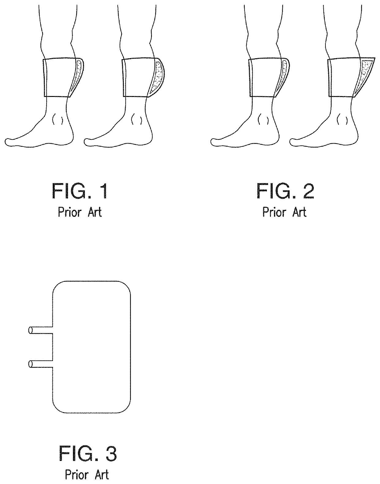
Some IPC devices do not themselves provide pneumatic pressure—they rely on external pneumatic controllers that are connected via a tube to a compression sleeve that provides the pressure to the tissue of the limb of the subject.
This design does present significant inconvenience and risk to both the patient and the hospital staff due to entanglements and the need to manage external cables and conduits.
However, many IPC devices do not have their own power sources, and must be connected to electrical outlets.
These non-mobile versions of IPCs are too bulky, and restrict the movement of the subject to a limited area, or in many cases, a stationary state.
Current mobile IPC devices that tubeless and have their own power sources (e.g., battery powered) provide too weak a pressure to ultimately be effectively, or fail to hold their charge for sufficient lengths of time to apply the needed therapy.
The former have inferior clinical outcomes, and the latter cause excessive work for nurse resources who must remove, recharge, and re-apply the IPC device.
In either case, currently available mobile IPC devices cannot be used continuously for a period of 18 hours in a day efficiently to meet the desired results as planned by physicians prescribing such course of treatment without being recharged while in use, requiring the user to be immobile.
In addition, the current IPC devices, mobile and immobile, present the risk of electrocution and other electrical fault conditions because of the need to be connected to wall power for at least time during operation of the IPC device.
For mobile patients, being tethered by an electrical cable to wall power is at least inconvenient and defeats the intent of a mobile device.
For bedridden patients, having a power source attached to the patient while in the bed and under covers exposes the patient to various electrical risks (electrocution, ground, user entanglement, trip hazards, wire breakage, accidental disconnection, confusion with other lines in the field and other phenomena).
Because of these risks, hospitals currently do not use mobile IPC devices where power cables are attached at any point to the patient.
In such instances, the IPCs are tethered to a computer in order to ensure that the patient is maintaining the treatment plan, severely impacting the quality of life of the patient.
In addition, many portable IPC devices are only configured to use with a single patient.
That is, once an IPC device is been used by a patient, for sanitary purposes, it cannot be used by additional users.
These devices are completely disposable and do not enable cleaning or recycling of the components.
The single-use nature of these mobile IPC devise requires the use of materials and components that are sourced for low cost and not for reliability or performance.
These lower-quality devices tend to have few features, cheap sleeves, and inexpensive controllers that result in variable performance that risk good patient outcomes.
The dissembled devise consists of a pneumatic controller and a sleeve with a very long pneumatic conduit hanging off to the side, which is difficult to manage and is a source of irritation to the user.
These hook and loop portable IPC devices typically have a loose and weak attachment between the pneumatic controller and the sleeve.
Such weak connections lead to attachment fails in several mechanical conditions that occur during normal use like vigorous leg movement or when the IPC device bumps into objects during ambulation.
Another drawback is that these fails over time lead to the hooks becoming broken or clogged with debris and / or the hook-receptive surface frays and loses the ability to attach to the hooks on the pneumatic controller.
The other IPC devices that use mechanical clasps to removably attach the controller to the sleeve suffer from the inconvenience of having to undue multiple mechanical attachments before the pneumatic controller can be removed from the sleeve.
The mechanical claps used for some of these devices do not appear to be robust.
Overall, the designs used for portable IPC devices allow for too much user error and lead to user frustration.
If the sleeve is not properly constructed to conduct heat and moisture away from the skin, the sleeve can cause the patient great discomfort.
If not properly constructed, skin irritations, caused by trapped heat and moisture, can result.
Prior art sleeves have also failed to conform to the complex user anatomy while maintaining sufficient mechanical integrity to hold the bladder in place during use and convey mechanical energy into the underlying tissues.
If the sleeve material is too compliant (flexible), the sleeve will stretch when the bladder inflates and the mechanical energy intended for tissue therapy will be made less effective by stretching the fabric instead of compressing the underlying tissues.
If the sleeve material is too stiff (rigid), the sleeve will not be able to wrap and accommodate the underlying tissue intending to be treated.
The wrinkled sleeve may enable the pneumatic bladder to migrate within the sleeve when inflated or the bladder could inflate within the wrinkled space and apply energy to the rigid sleeve material instead of the underlying tissues, thus reducing the user's therapeutic experience.
If the bladder is improperly located or allowed to migrate, the patient will not benefit from the IPCD therapy.
Adding new weld seals also increases the risk of pneumatic leaks.
Another liability of these seals within the bladder's inflated region is the increase in geometric complexity and the likelihood of introducing stress raisers in the inflated envelope that can lead to either burst failures or fatigue failures (cyclic inflation causes mechanical damage due to the presence of a weld that accumulates over time).
That is, there is no way to remove the bladder from the sleeve and / or the other components of the IPC device, so that when the sleeve fails, the bladder is discarded with the sleeve.

Method used


Image

  • Intermittent Pneumatic Compression System
  • Intermittent Pneumatic Compression System
  • Intermittent Pneumatic Compression System

Examples


Embodiment Construction

[0071]Embodiments of the present invention will be described more fully hereinafter with reference to the accompanying drawings, in which embodiments of the invention are shown. This invention may, however, be embodied in many different forms and should not be construed as limited to the embodiments set forth herein; rather, these embodiments are provided so that this disclosure will be thorough and complete, and will fully convey the scope of the invention to those skilled in the art.

[0072]In the following description, numerous specific details are set forth. However, it is to be understood that embodiments of the invention may be practiced without these specific details. In other instances, well-known methods, structures and techniques have been shown in detail in order not to obscure an understanding of this description.

[0073]The present invention is directed towards a mobile intermittent pneumatic compression (IPC) device 20, as shown in FIG. 4, for use in an IPC system 10. The ...


PUM


Abstract

The invention is directed at an intermittent pneumatic compression (IPC) system that is modular in nature and allows mobility for subjects utilizing the system. In an aspect, the IPC system utilizes a mobile IPC device. The mobile IPC devices is an easy to use portable device that can be mounted onto a limb of a subject. The modular mobile IPC device includes an independent power source, allowing subjects to be mobile while the IPC device is operating. In an aspect, the mobile IPC device also ensures compliance of following the prescribed treatment.

Description

REFERENCE TO RELATED APPLICATION[0001]This application claims priority to United Stated Non-Provisional application Ser. No. 16 / 655,987, filed Oct. 17, 2019, and U.S. Provisional Application No. 62 / 746,799, filed on Oct. 17, 2018, which are relied upon and incorporated in their entirety by reference.FIELD OF INVENTION[0002]This invention generally relates to an intermittent pneumatic compression device for use with limbs to improve venous circulation.BACKGROUND OF THE INVENTION[0003]Intermittent pneumatic compression (IPC) devices are used to improve venous circulation in limbs. In most aspects, IPC devices are used to improve venous circulation in the legs of patient suffering edema, or patients who may be at risk for developing blood clots in the deep veins of the leg, typically due to decreased blood flow and a higher likelihood of clotting due to low blood flow. IPC devices intermittently provide high pressure to the tissues of the limb, forcing fluids such as blood and lymph ou...

Claims


Application Information

Patent Timeline
Patent Type & Authority Applications(United States)
IPC IPC(8): A61H9/00
CPCA61H9/0078A61H2201/0103G16H10/65A61H2201/5058A61H2201/0157A61H2201/164A61H2201/165A61H2201/501A61H2201/5043A61H2201/0107A61H2201/1207A61H2201/1409A61H2201/1645A61H2201/1688A61H2201/1697A61H2201/5007A61H2201/5033A61H2201/5064A61H2201/5082A61H2201/5097A61H2205/10A61H2205/106A61H2209/00G16H20/30G16H40/63G16H40/67
Inventor PARKER, RICHARD L.BUCK, SARAH R.PATEL, DERSHIKAFISHER, MICHAEL A.HILBORN, NICHOLAS L.BONISTALLI, DANIELSTRANE, PATRICK
Owner PEACHTREE MEDICAL PROD LLC
Why Eureka
Try Eureka