Vein filter

a technology of vein filter and filter body, applied in the field of vein filter, can solve the problems of shock and even death, interference with oxygenation of blood, and limited use of medications,

Active Publication Date: 2005-07-28
ARGON MEDICAL DEVICES
View PDF98 Cites 164 Cited by
  • Summary
  • Abstract
  • Description
  • Claims
  • Application Information

AI Technical Summary

Benefits of technology

[0023] The mounting portion preferably includes vessel engaging members in the form of hooks to enhance retention of the filter. In one embodiment, the vessel engaging members include a first set of hooks and a second set of hooks, each set of hooks being positioned at an end of the mounting portion or second terminal end, and the first set of hooks having a transverse dimension greater than a transverse dimension of the second set of hooks. In one embodiment, the first set of hooks is axially offset from the second set of hooks, and each hook of the second set is axially offset with respect to other hooks of the second set.

Problems solved by technology

These clots typically originate in the veins of the lower limbs and can migrate through the vascular system to the lungs where they can obstruct blood flow and therefore interfere with oxygenation of the blood.
Pulmonary embolisms can also cause shock and even death.
These medications, however, have limited use since they may not be able to be administered to patients after surgery or stroke or given to patients with high risk of internal bleeding.
Also, this medication approach is not always effective in preventing recurring blood clots.
However, this approach is an invasive surgical procedure, requiring an abdominal incision and general anesthesia and frequently causing vessel thrombosis and lower extremity swelling.
Also, there is a lengthy patient recovery time and additional hospital and surgeon expenses associated with this major surgery.
In fact, oftentimes, the patients requiring the surgery are unhealthy and the major surgery and general anesthesia poses a risk in and of itself.

Method used


Image

  • Vein filter
  • Vein filter
  • Vein filter

Examples


Embodiment Construction

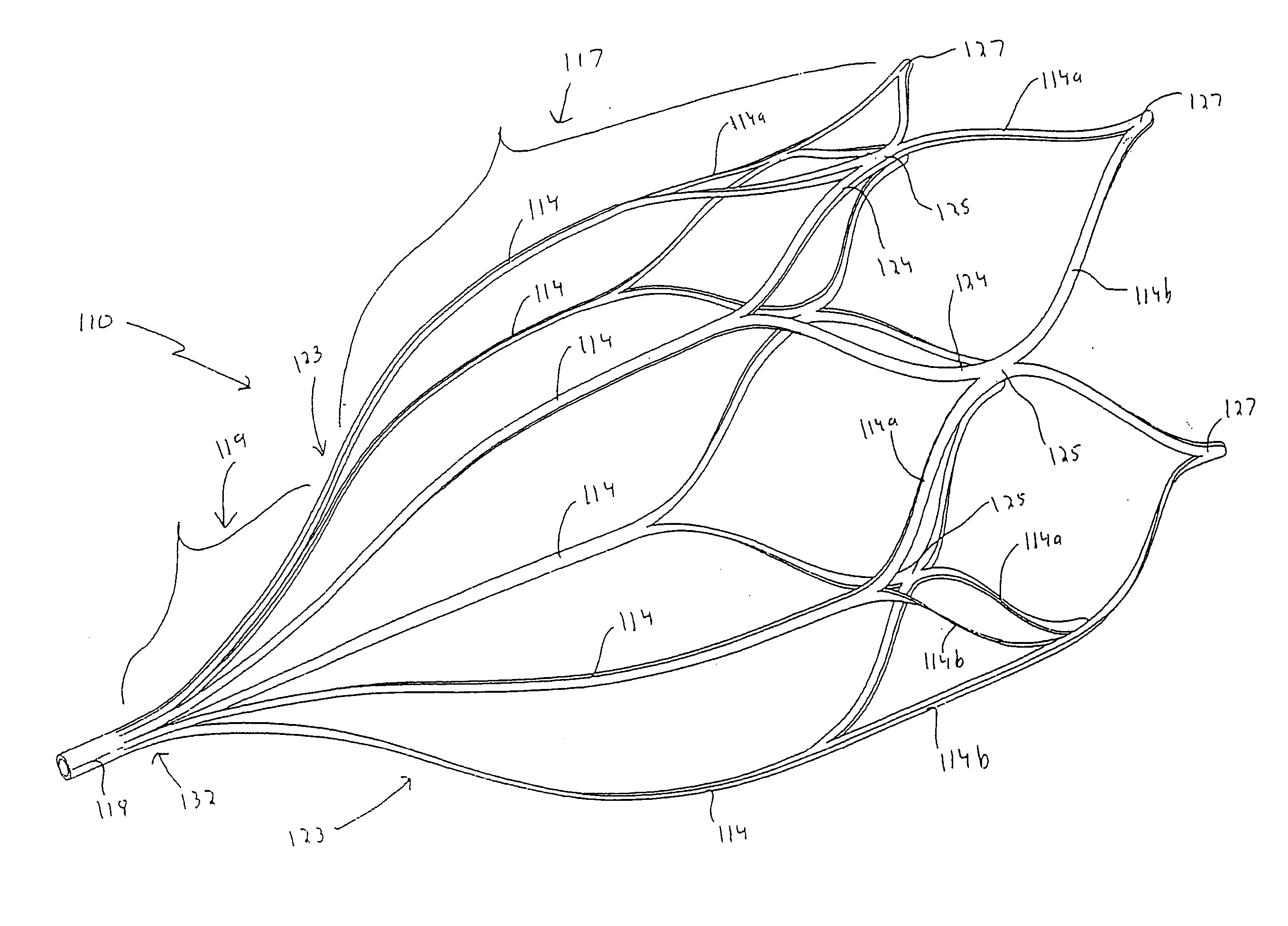
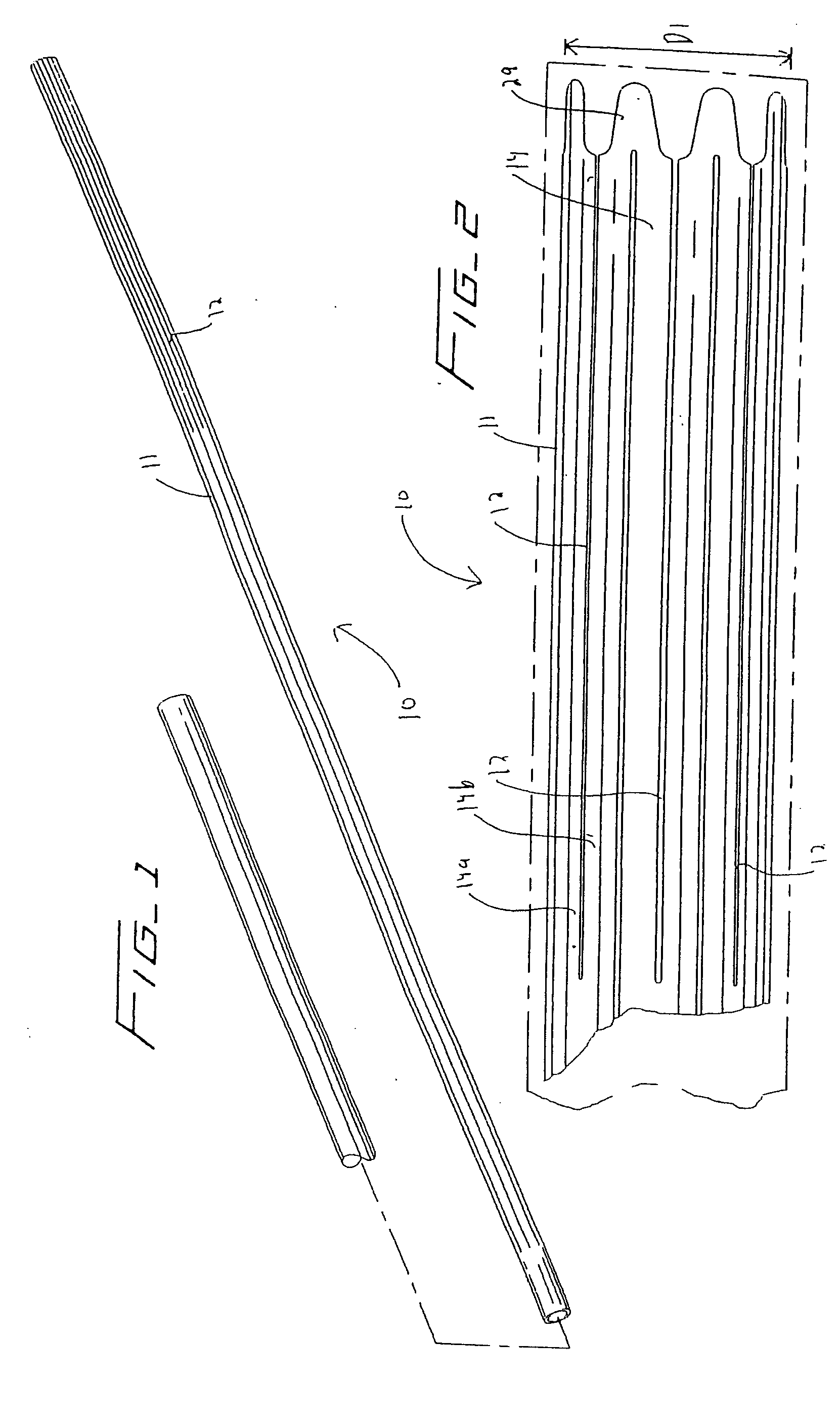
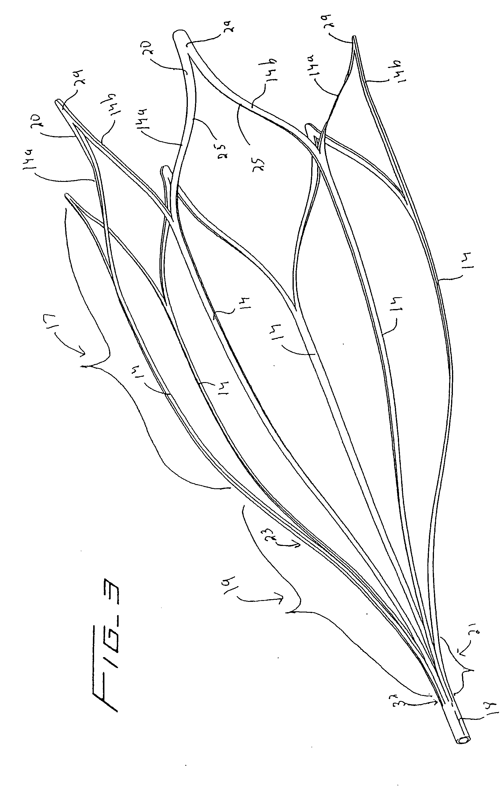
[0075] Turning now to the drawings, wherein like reference numerals identify similar or like components throughout the several views, various embodiment of the vein filter of the present invention are described for placement within the inferior vena cava to capture blood clots or other particles which could otherwise pass to the lungs.

[0076] The filter is movable from a low profile collapsed configuration to facilitate insertion through the delivery sheath to a larger expanded placement configuration to enable atraumatic engagement with the vessel walls to secure (mount) the filter within the inferior vena cava. The filter is preferably substantially bell-shaped and preferably has a flared or mounting region (portion / section) and a filtering region (portion / section). As described in more detail below, the filtering portion has inwardly directed struts, terminating in a converging region, thereby directing particles toward the central axis of the filter. By directing the particles t...


PUM


Abstract

A vessel filter comprising a first region and a second region wherein the filter is movable between a collapsed position for delivery to the vessel and an expanded position for placement within the vessel. A first region has a filter portion having a converging region to direct particles toward the center of the filter and the second region is flared in the expanded position to have a transverse dimension increasing toward a second end portion opposite the first end portion. The second region includes a vessel engaging portion at the second end portion. The first region includes a plurality of spaced apart elongated struts with adjacent struts being joined.

Description

[0001] This application claims priority from provisional application Ser. No. 60 / 572,274, filed May 18, 2004, and is a continuation-in-part of application Ser. No. 10 / 805,796 filed Mar. 22, 2004, which claims priority from provisional application Ser. No. 60 / 538,379, filed Jan. 22, 2004. The entire contents of these applications are incorporated herein by reference.BACKGROUND [0002] 1. Technical Field [0003] This application relates to a vascular filter and more particularly to a vein filter for capturing blood clots within the vessel. [0004] 2. Background of Related Art [0005] Passage of blood clots to the lungs is known as pulmonary embolism. These clots typically originate in the veins of the lower limbs and can migrate through the vascular system to the lungs where they can obstruct blood flow and therefore interfere with oxygenation of the blood. Pulmonary embolisms can also cause shock and even death. [0006] In some instances, blood thinning medication, e.g. anticoagulants suc...

Claims


Application Information

Patent Timeline
Patent Type & Authority Applications(United States)
IPC IPC(8): A61F2/00A61F2/01A61F2/02A61F2/06A61M29/00
CPCA61B2017/2215A61F2/01A61F2/013A61F2002/011A61F2002/018A61F2230/005A61F2220/0016A61F2250/0059A61F2002/016A61F2230/008A61F2002/8483A61F2/011A61F2/0105
Inventor THINNES, JOHN H. JR.MCGUCKIN, JAMES F. JR.DEFONZO, STEPHAN A.CARTER, LINDSAY L.
Owner ARGON MEDICAL DEVICES
Why Eureka
Try Eureka