Method and apparatus for copying and backup in storage systems

Inactive Publication Date: 2005-07-28
HITACHI LTD
View PDF23 Cites 61 Cited by
  • Summary
  • Abstract
  • Description
  • Claims
  • Application Information

AI Technical Summary

Benefits of technology

[0008] A storage system which implements the invention includes a set of primary storage volumes, a set of replication storage volumes which improve the reliability of the storage system, a memory for storing information regarding at least one bou

Problems solved by technology

In some circumstances when a replication volume is assigned into the same failure boundary as a source volume, for example it is assigned to the same error correction group, a single failure may impact both the original volume and the replication volume.
In another situation when daily backups are performed, if the storage v

Method used


Image

  • Method and apparatus for copying and backup in storage systems
  • Method and apparatus for copying and backup in storage systems
  • Method and apparatus for copying and backup in storage systems

Examples


Embodiment Construction

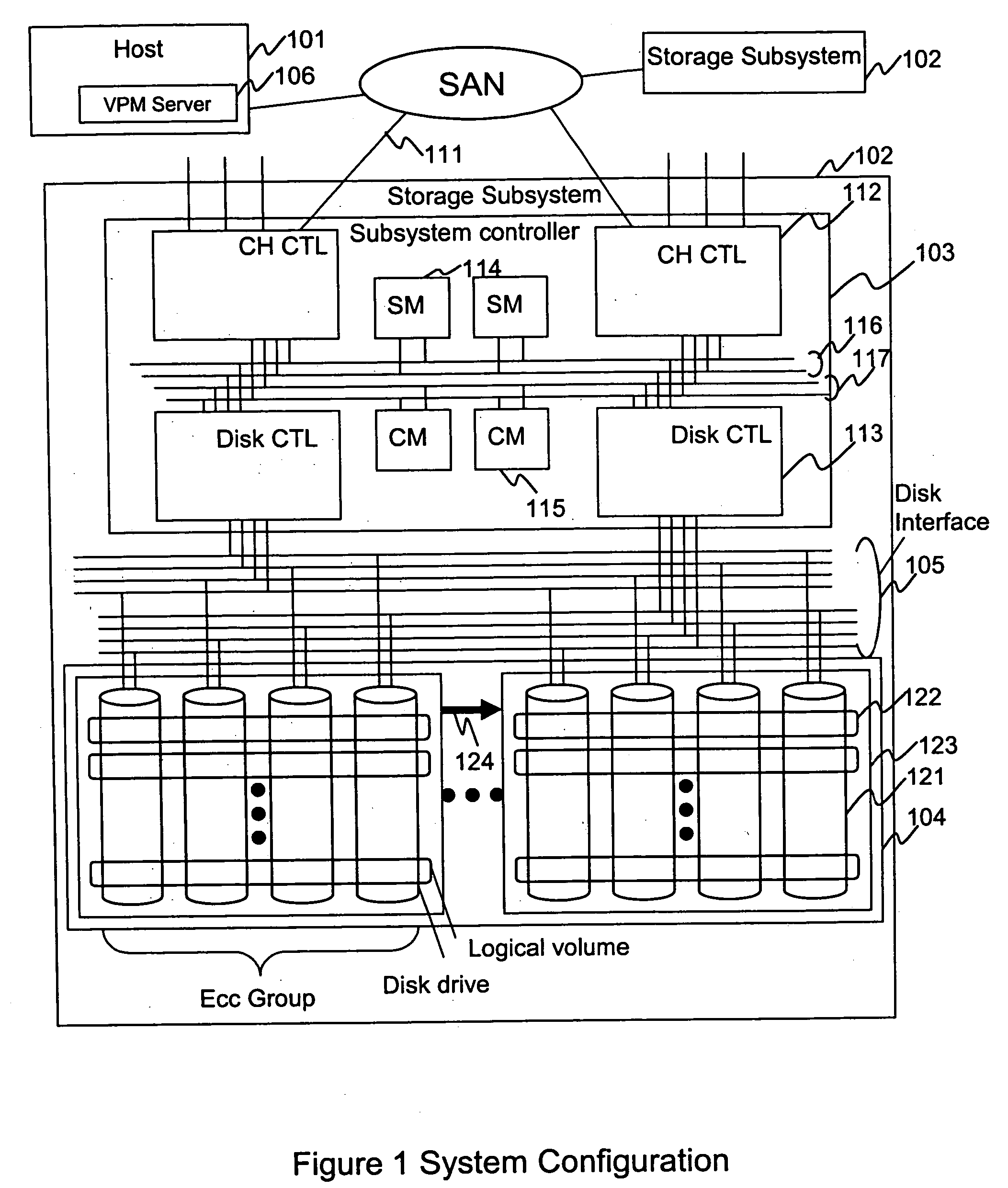
[0025]FIG. 1 is a block diagram of a storage system. As shown, host 101 and storage subsystem 102 are connected with an input / output interface 111. Interface 111 can be provided by a fibre channel, ESCON etc. The number of host and storage subsystems 102 is arbitrary. In FIG. 1 a more detailed view of storage subsystem 102 is provided. Subsystem 102 includes a subsystem controller 103 and a disk enclosure 104. The subsystem controller 103 includes channel controllers 112, disk controllers 113, a shared memory 114 and a cache memory 115. These components are usually configured as a pair, i.e. duplicates of each other. Generally each member of the pair belongs to a different power boundary to provide assurance that a single failure of the power supply does not disable both subsystem controllers.

[0026] Internal connections 116 and 117 connect the two controllers, the shared memory 114 and the cache memory 115. The shared memory stores control data for the storage system 102. The cache...


PUM


Abstract

A technique is described for controlling a storage system in which primary storage volumes and replication storage volumes are present. A boundary of a potential failure of the primary storage volumes and the replication storage volumes is determined, and using that boundary, replication storage volumes are assigned to assure that at least some of them are outside the failure boundary.

Description

BACKGROUND OF THE INVENTION [0001] This invention relates to storage systems, and in particular to storage system management in which failure boundaries are taken into consideration when assigning storage volumes. [0002] Large area storage systems are now well known. In these systems massive amounts of data are capable of being stored and automatically backed up or replicated at remote locations to provide increased data reliability. In such systems, large numbers of hard disk drives and sophisticated error correction and redundancy technology are commonly employed. The systems generally operate under control of local and remote application software. Hitachi, Ltd., the assignee of this application, provides local replication software known as “Shadow Image,” and provides remote replication software known as “True Copy.” Remote copy techniques for implementation of software such as this are described in U.S. Pat. No. 5,978,890; U.S. Pat. No. 6,240,494; U.S. Pat. No. 6,321,292; and U....

Claims


Application Information

Patent Timeline
IPC IPC(8): G06F12/16
CPCG06F11/2069G06F11/004
Inventor WATANABE, NAOKI
Owner HITACHI LTD
Why Eureka
Try Eureka